

Covered stent
Patent Information
- Authority / Receiving Office
- CN · China
- Current Assignee / Owner
- SUZHOU ZENITH VASCULAR SCITECH LTD
- Publication Date
- 2020-12-04
Smart Images
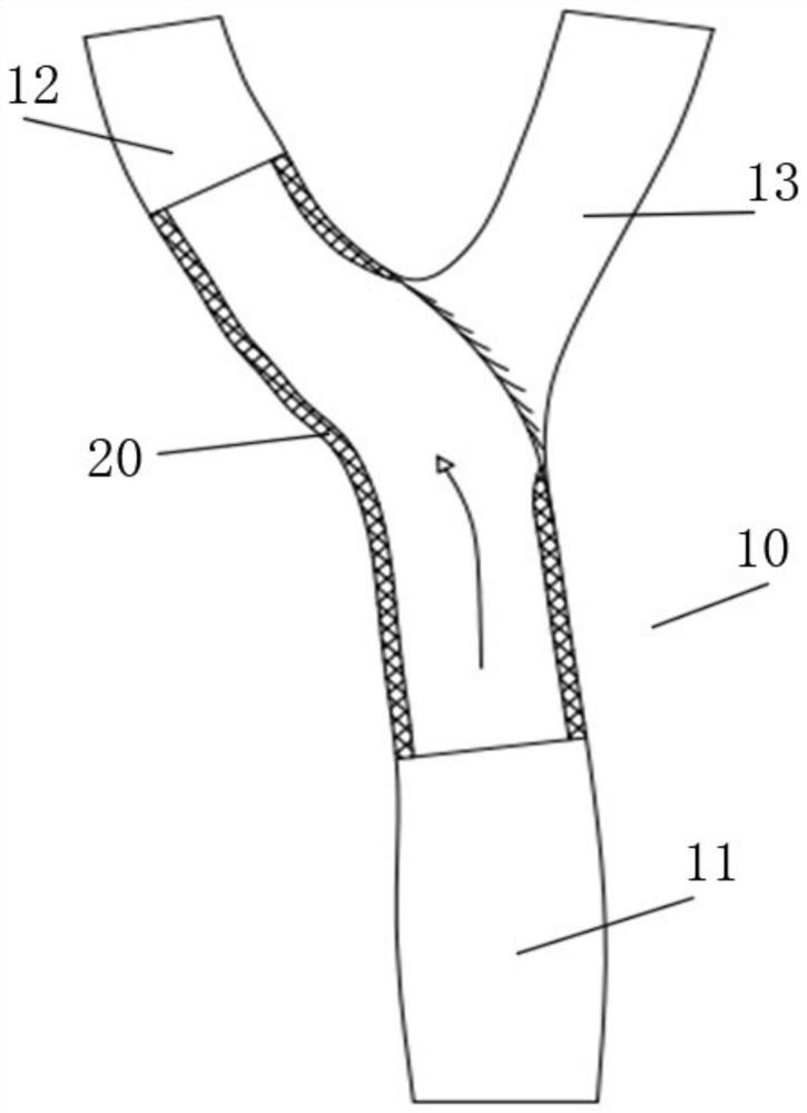
Figure 1 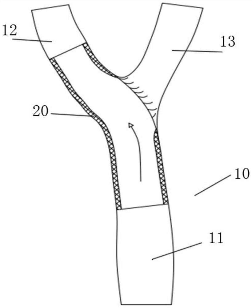
Figure 2 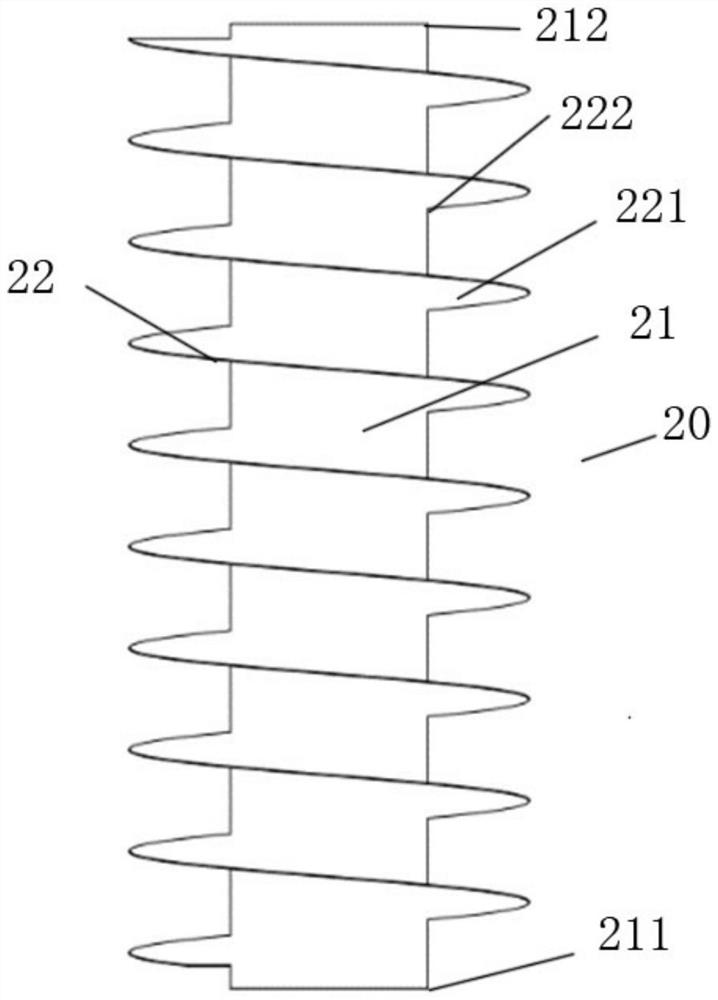
Figure 3
Abstract
Description
technical field
[0001] The invention belongs to the technical field of medical devices, and in particular relates to a covered stent. Background technique
[0002] Cerebrovascular disease is a major disease that threatens human health today, and is the third leading cause of death after cardiovascular disease and tumors. Among them, 25% of ischemic strokes are related to carotid artery stenosis or occlusion.
[0003] The treatment of carotid artery stenosis is mainly divided into drug therapy, carotid endarterectomy, and carotid artery stenting. Among them, carotid artery stenting has the advantages of simple operation, less trauma, and fewer complications, and is currently one of the effective methods for treating carotid artery stenosis.
[0004] The carotid artery is divided into the common carotid artery, the external carotid artery and the internal carotid artery. The common carotid artery, the external carotid artery and the internal carotid artery have a Y-shaped bif...