Tunnel dust removal equipment

A technology for dust removal equipment and tunnels, which is used in mining equipment, dust prevention, and dispersed particle filtration.

Pending Publication Date: 2020-12-04
SANY HEAVY EQUIP
View PDF0 Cites 0 Cited by
  • Summary
  • Abstract
  • Description
  • Claims
  • Application Information

AI Technical Summary

Problems solved by technology

[0004] However, in the above-mentioned dust removal equipment, the air volume and wind speed of the dusty air entering the dust removal box to each cluster filter element are different, and the air distribution uniformity in the dust removal box is poor, resulting in different utilization rates of each filter element. The degree of wear is inconsistent, resulting in poor dust removal effect of the dust removal equipment

Method used


Image

  • Tunnel dust removal equipment
  • Tunnel dust removal equipment
  • Tunnel dust removal equipment

Examples


Embodiment Construction

[0049] In describing the present invention, it should be understood that the terms "center", "longitudinal", "transverse", "length", "width", "thickness", "upper", "lower", "front", " Orientation or position indicated by "back", "left", "right", "vertical", "horizontal", "top", "bottom", "inner", "outer", "clockwise", "counterclockwise", etc. The relationship is based on the orientation or positional relationship shown in the drawings, and is only for the convenience of describing the present invention and simplifying the description, rather than indicating or implying that the referred device or element must have a specific orientation, be constructed and operated in a specific orientation, therefore It should not be construed as a limitation of the present invention.

[0050] In addition, the terms "first" and "second" are used for descriptive purposes only, and cannot be interpreted as indicating or implying relative importance or implicitly specifying the quantity of indic...


PUM


Abstract

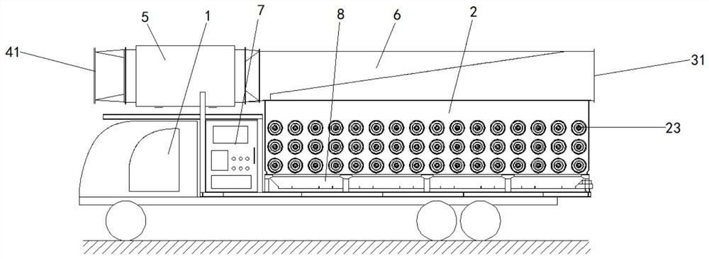
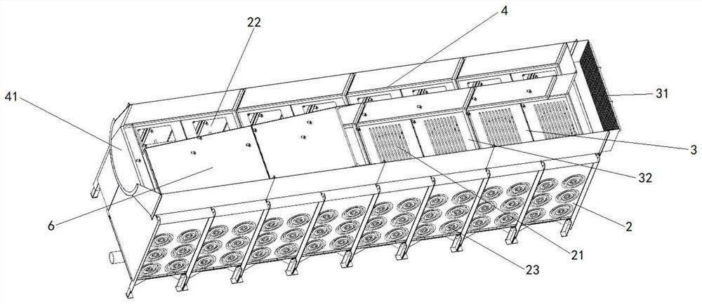
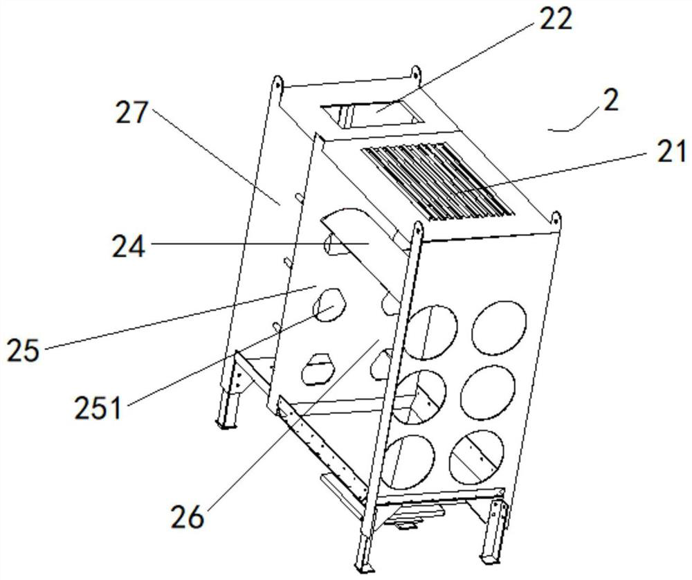
The invention discloses tunnel dust removal equipment, relates to the technical field of tunnel construction, and mainly aims to improve the air distribution uniformity of the dust removal equipment,prolong the service life of a filter cartridge and improve the dust removal effect of the dust removal equipment. According to the main technical schemes of the invention, the tunnel dust removal equipment comprises a vehicle body, a plurality of dust removal modules, an air inlet pipeline, an air outlet pipeline and an air suction part; the dust removal modules are arranged on the vehicle body side by side; each dust removal module comprises a first air inlet and a first air outlet; the areas of the first air inlets of the dust removal modules are equal; and filter cartridges are arranged inthe dust removal modules; the air inlet pipeline is arranged on the vehicle body and communicated with the first air inlets of the dust removal modules; the air inlet pipeline comprises a second air inlet and a plurality of air distribution plates which are connected with one another and are in one-to-one correspondence with the first air inlets; the heights of the air distribution plates are gradually reduced along with the increase of the distance between the air distribution plates and the second air inlet; the air outlet pipeline is arranged on the vehicle body and comprises a second air outlet; the air outlet pipeline is communicated with the first air outlets of the dust removal modules; and the air suction part is communicated with the second air outlet.

Description

technical field [0001] The invention relates to the technical field of dust removal equipment, in particular to a tunnel dust removal equipment. Background technique [0002] During the construction of the tunnel, a large amount of dust will be generated at the construction site, and the dust will overflow from the tunnel mouth, which will have a bad impact on the surrounding environment and will also cause harm to human health. [0003] At present, dust removal equipment is usually used to clean the dust generated in the tunnel. The dust removal equipment usually includes a pull-out power system and a dust removal box connected to the power system, and several cluster filter elements are arranged in the dust removal box. Each cluster filter element is evenly distributed. Distributed in the flow direction of the dust to filter the dusty air entering the dust box to obtain clean air. [0004] However, in the above-mentioned dust removal equipment, the air volume and wind spe...

Claims


Application Information

Patent Timeline
Patent Type & Authority Applications(China)
IPC IPC(8): B01D46/24B01D46/00E21F5/20
CPCB01D46/2411B01D46/0041E21F5/20B01D46/56
Inventor 樊志家李洪亮沈洪波
Owner SANY HEAVY EQUIP
Why Eureka
Try Eureka