
Intake devices and semiconductor processing equipment

An air intake device and gas technology, which is used in semiconductor/solid-state device manufacturing, electrical components, gaseous chemical plating, etc. efficiency, improve the uniformity of airflow distribution, and improve the effect of process efficiency

Active Publication Date: 2019-04-23
BEIJING NAURA MICROELECTRONICS EQUIP CO LTD
View PDF4 Cites 0 Cited by
  • Summary
  • Abstract
  • Description
  • Claims
  • Application Information

AI Technical Summary

Problems solved by technology

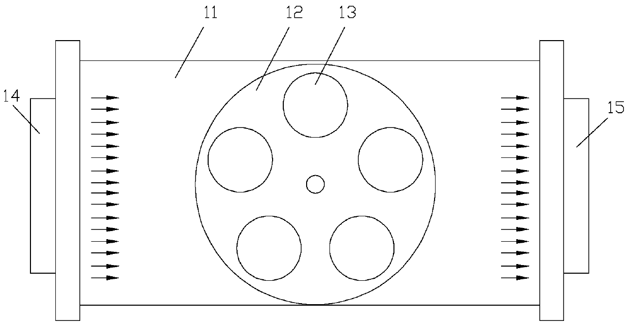
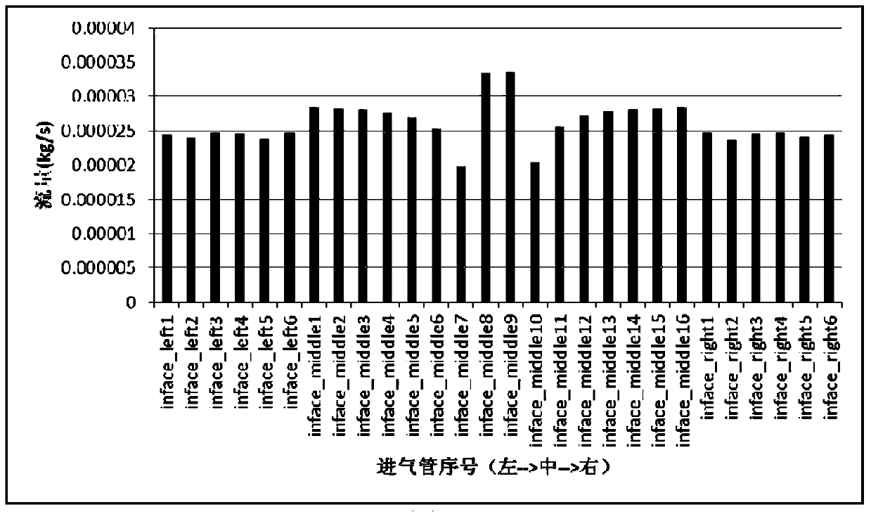
like Figure 4 As shown, due to the influence of the jet flow effect, vortices will appear near the gas inlet where the gas flow velocity is different, resulting in uneven gas flow distribution in the reaction chamber
[0007] Although 28 regulating valves can be used to adjust the air flow of 28 air outlets individually to compensate for the flow rate difference of each air outlet, this adjustment method is not only a large workload and complicated, but also because each air outlet is closed. The overall air flow uniformity of the reaction chamber is affected, and there are too many process variables, which is not conducive to the stable control of the process, and the effectiveness and efficiency of this adjustment method are not high, and it is difficult to meet the continuous production requirements

Method used


Image

  • Intake devices and semiconductor processing equipment
  • Intake devices and semiconductor processing equipment
  • Intake devices and semiconductor processing equipment

Examples


no. 1 example

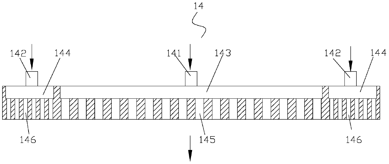
[0046] Figure 5A It is a schematic diagram of the air intake device provided by the first embodiment of the present invention. see Figure 5A , the air intake device comprises an air inlet 20 and an air inlet chamber 100, both of which are located on one side of the reaction chamber 50, wherein the air inlet chamber 100 is used to flow the reaction gas flowing out from the air inlet 20 in the horizontal direction (Y direction) into the reaction chamber 50. The so-called horizontal direction refers to the direction parallel to the surface of the processed workpiece placed in the reaction chamber 50 . During the process, the reaction gas flows into the reaction chamber 50 from one side of the reaction chamber 50 along the horizontal direction, and when it passes through the surface of the workpiece to be processed, it undergoes a chemical reaction with it, and the residual gas after the reaction is accompanied by the carrier gas. It is discharged from the other side of the r...

no. 2 example

[0065] Figure 6A The schematic diagram of the air intake device provided by the second embodiment of the present invention. see Figure 6A Compared with the above-mentioned first embodiment, the gas inlet device provided in this embodiment differs only in that: in this embodiment, the 1st to N-1 level uniform gas layers convey the reaction gas step by step along the vertical direction, and the 1st to N-1 The N-level uniform gas layer transports the reaction gas in the horizontal direction. The so-called vertical direction refers to the direction perpendicular to the surface of the processed workpiece placed in the reaction chamber.

[0066] specifically, Figure 6B It is a sectional view of the air intake device provided by the second embodiment of the present invention. Figure 6C for Figure 6B Sectional view along line A-A. Please also refer to Figure 6B and 6C , for the 1st to N-1 level gas distribution layers in the air intake chamber 100, compared with the 1st ...

no. 3 example

[0071] Figure 7A It is a schematic diagram of the air intake device provided by the third embodiment of the present invention. see Figure 7A Compared with the above-mentioned second embodiment, the air intake device provided by this embodiment is only different in that: N=3, and in the third-level gas uniform layer, the number of shunts allocated by each subunit is four, That is, each sub-unit 43 in the third-level gas homogenization layer directly and evenly distributes the branches allocated by all the sub-units in the second-level gas homogenization layer into four branches along the direction perpendicular to the direction of conveying the reaction gas in one-to-one correspondence. .

[0072] specifically, Figure 7B It is a sectional view of the air intake device provided by the third embodiment of the present invention. see Figure 7B , as for the first to second level gas homogenization layers in the air intake chamber 200 , compared with the first to second leve...


PUM


Abstract

The invention provides a gas inlet device and a semiconductor machining device. The gas inlet device comprises a gas inlet and a gas inlet chamber. The gas inlet chamber comprises N stages of gas uniformizing layers. The first stage of gas uniformizing layer comprises one subunit which is used for evenly distributing reaction gas coming from the gas inlet into two branches in the direction perpendicular to the reaction gas conveying direction. The ith stage of gas uniformizing layer comprises a plurality of subunits which are used for evenly distributing all branches distributed by all subunits in the i-1th stage of gas uniformizing layer into at least two branches again in a one-to-one correspondence manner in the direction perpendicular to the reaction gas conveying direction, wherein the number of the branches is an even number, and i is equal to 2, 3,...N. All subunits in the Nth stage of gas uniformizing layer are used for conveying all branches which are independently distributed into a reaction chamber. By means of the gas inlet device, the distribution uniformity of gas flow in the reaction chamber can be improved, effectiveness and efficiency of gas flow regulation can be improved, and therefore the process efficiency can be improved.

Description

technical field [0001] The invention relates to the technical field of semiconductor processing, in particular to an air intake device and semiconductor processing equipment. Background technique [0002] The basic principle of chemical vapor deposition epitaxial growth is to transport the reaction gas into the reaction chamber, and make the reaction gas react chemically on the surface of the substrate by means of heating, and the obtained growth atoms are deposited on the surface of the substrate, and grow to form single Crystal thin film. In the process of chemical vapor deposition epitaxial growth, gas transportation and control systems (including pipelines, flow rates and valves, etc.) are usually used to ensure timely and accurate transportation of reaction gases to the reaction chamber. [0003] In order to meet the requirements of uniform doping and uniform thickness required for growing thin films, and to improve the concentration and thickness uniformity of the thi...

Claims


Application Information

Patent Timeline
Patent Type & Authority Patents(China)
IPC IPC(8): C23C16/455H01L21/02H01J37/32
Inventor 马志芳张慧吴军
Owner BEIJING NAURA MICROELECTRONICS EQUIP CO LTD
Learn More