Efficient grinding machine

A grinding machine, high-efficiency technology, applied in the direction of grain processing, etc., can solve the problems of uneven speed of materials, difficult to control gaps, unevenness, etc., to reduce the probability of screen blockage, narrow particle size distribution of materials, increase The effect of filter area

Pending Publication Date: 2020-12-04
广东京驰智能装备有限公司
View PDF0 Cites 3 Cited by
  • Summary
  • Abstract
  • Description
  • Claims
  • Application Information

AI Technical Summary

Problems solved by technology

However, the current grinding machine cannot be used for multiple purposes, and cannot meet the requirements of diversification of chemical products, and it is extremely inconvenient during the installation and maintenance of the after-sales process, which seriously affects the use efficiency and the economic benefits brought by the equipment to customers. maximization of
[0004] In addition, most of the traditional separation screens are spirally wound with trapezoidal stainless steel wires. Therefore, due to uneven materials and different speeds during the winding process, it will be difficult to control the gap evenly. Unevenness, these all make it difficult to control the quality of the separation screen, especially the gap below 0.1mm is even more difficult to make. During use, the grinding medium hits the gap, and the cross-section is trapezoidal, so the traditional separation screen Easy to leak beads and not durable

Method used


Image

  • Efficient grinding machine
  • Efficient grinding machine
  • Efficient grinding machine

Examples


Embodiment Construction

[0030] The preferred embodiments of the present invention will be described below with reference to the accompanying drawings. It should be understood that the preferred embodiments described herein are only used to illustrate and explain the present invention, but not to limit the present invention.

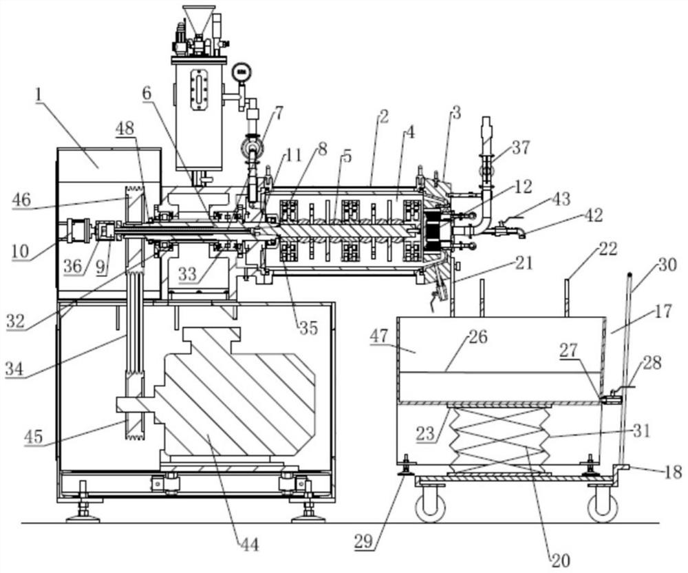
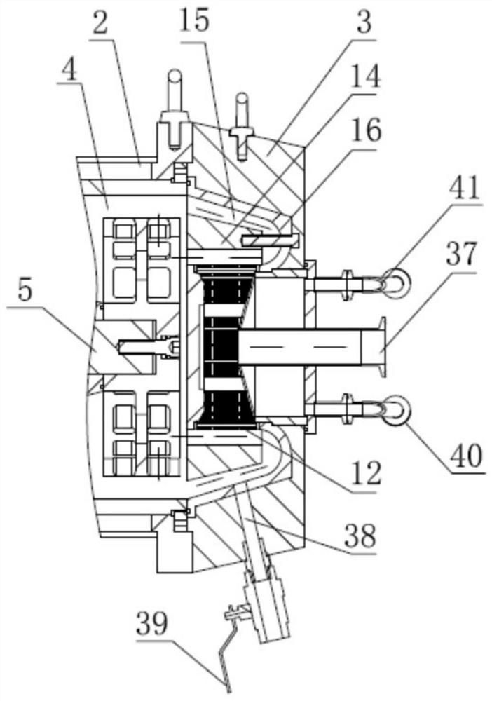
[0031] like Figures 1 to 6As shown, a high-efficiency grinding machine includes a frame 1, including a frame 1 and a grinding barrel 2. The front end of the grinding barrel 2 is detachably provided with an end cover 3, and the end cover 3 is installed on the grinding barrel 2 by bolting. The front end of the grinding barrel 2 and the end cover 3 are sealed to form a grinding cavity 4, the grinding cavity 4 is provided with a grinding rotor 5, a rotating shaft 6 is rotated on the frame 1, and the rotating shaft 6 is provided with a first bearing 32 and a second The bearing 33, the first bearing 32 and the second bearing 33 are installed on the bearing seat of the frame 1, so tha...


PUM


Abstract

The invention provides an efficient grinding machine which comprises a rack, a grinding barrel, an end cover and a grinding rotor, wherein the end of the grinding rotor is connected with one end of apull rod, the other end of the pull rod is connected with a rotary joint, a hydraulic cylinder is arranged beside the rotary joint, a gap is formed between the rotary joint and the hydraulic cylinder,a clamping jaw is arranged at the end of the pull rod, the end of the grinding rotor is detachably connected to the clamping jaw, a screen is arranged at the front end of the grinding rotor, a large-flow dynamic anti-blocking separation system is further formed at the position of the screen, and a movable disassembly mechanism is further arranged below the rack. The grinding machine has the beneficial effects that the grinding rotor is detachably connected to the pull rod, and after the grinding barrel is opened, the pull rod can be pushed by controlling the hydraulic cylinder to push out thegrinding rotor, so that cleaning, maintenance and replacement of the grinding rotor are facilitated; and the grinding machine is further provided with the dynamic anti-blocking separation system andthe movable disassembly mechanism, and the purposes of large-flow blockage prevention and convenient disassembly are achieved.

Description

technical field [0001] The invention relates to the technical field of wet grinding equipment, in particular to a high-efficiency grinding machine. Background technique [0002] In the grinding equipment, the beads are usually driven by a dispersing disc, a rotor with blades or a turbine to move at a high speed. The beads are squeezed, collided and hit each other to disperse, shear and crush the material, so as to realize the fine grinding of the particles, and pass the screen to remove the particles. The ground material is separated from the unground material and beads, so that the ground material is output. Since its inception, the grinding equipment has won the reputation of researchers and business owners in the field of ultra-fine materials due to its excellent performance. With the rapid increase in the market demand for new energy and new materials, the requirements for its performance and quality are also increasing. Strict, especially developed countries such as Eu...

Claims


Application Information

Patent Timeline
Patent Type & Authority Applications(China)
IPC IPC(8): B02C17/10B02C17/18B02C23/10B02C17/24B02C23/28
CPCB02C17/10B02C17/18B02C17/184B02C17/1875B02C17/24
Inventor 陈公佐王蓉詹先华
Owner 广东京驰智能装备有限公司
Why Eureka
Try Eureka