Heat exchanger cooling structure forming manufacturing method
A technology of cooling structure and manufacturing method, applied in the direction of manufacturing tools, heat exchange equipment, feeding devices, etc., can solve the problems of copper tube deformation, high requirements, uneven force, etc., to eliminate looseness, improve forming effect and Quality, the effect of ensuring precision
- Summary
- Abstract
- Description
- Claims
- Application Information
AI Technical Summary
Problems solved by technology
Method used
Image

Examples
Embodiment Construction
[0036] In order to make the technical means, creative features, goals and effects achieved by the present invention easy to understand, the present invention will be further elaborated below in conjunction with specific drawings. It should be noted that, in the case of no conflict, the embodiments and Features in the embodiments can be combined with each other.
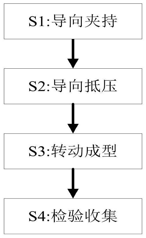
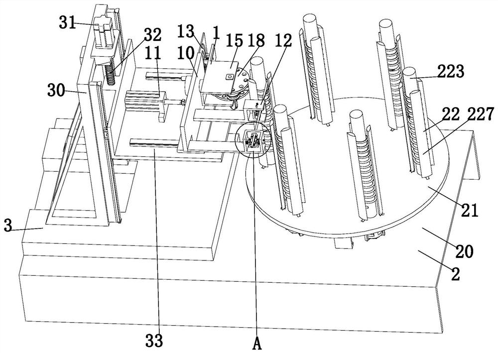
[0037] Such as Figure 1 to Figure 12 As shown, a heat exchanger cooling structure molding manufacturing method, which uses a heat exchanger cooling structure molding equipment, the molding equipment includes a pressure auxiliary mechanism 1, an intermittent indexing mechanism 2 and a displacement mechanism 3, using the above The specific processing method of the forming equipment for the forming and manufacturing of the cooling structure of the heat exchanger is as follows:
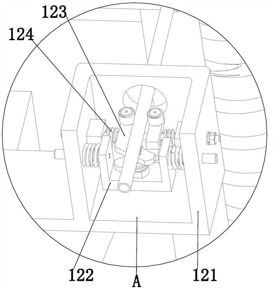
[0038] S1. Guide clamping: the cooling copper tube is clamped and slide-guided by the floating pinch unit 12, and the horizontal and vertical ...
PUM
 Abstract
Description
Claims
Application Information