Steel bar cutting machine device

A cutting machine and steel bar technology, applied in the field of steel bar cutting machine devices, can solve problems such as affecting work efficiency, unable to adjust the radius of steel bars to be cut, etc.

Inactive Publication Date: 2020-12-04
杭州圣埃蒂机械科技有限公司
View PDF0 Cites 1 Cited by
  • Summary
  • Abstract
  • Description
  • Claims
  • Application Information

AI Technical Summary

Problems solved by technology

[0002] The demand for steel is increasing day by day in today's society, and the demand for cutting machines for steel bars is also increasing accordingly. Most of the steel bar cutting machines on the market can only cut several fixed specifications of steel bars and cannot meet the radius requirements of the cut steel bars. Adjustment, and most of the cutting machines can not automatically adjust the cutting length of the steel bar to be cut, and the cutting length of the steel bar to be cut can be automatically cut, which seriously affects the work efficiency for a long time

Method used


Image

  • Steel bar cutting machine device
  • Steel bar cutting machine device
  • Steel bar cutting machine device

Examples


Embodiment Construction

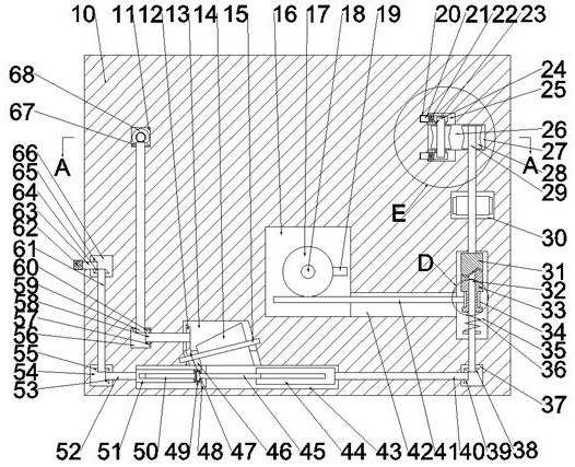
[0019] Combine below Figure 1-6 The present invention is described in detail, wherein, for the convenience of description, the orientations mentioned below are defined as follows: figure 1 The up, down, left, right, front and back directions of the projection relationship itself are the same.

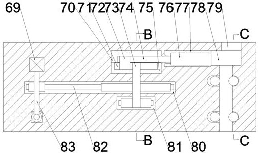
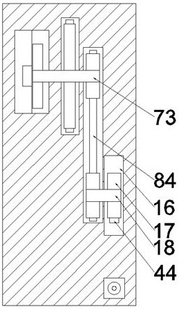
[0020]A steel cutting machine device described in conjunction with accompanying drawings 1-6 includes a box body 10, an intermittent transmission chamber 16 is provided inside the box body 10, and an intermittent transmission belt chamber 81 is provided on the rear side of the intermittent transmission chamber 16, so that The front end wall of the intermittent transmission belt chamber 81 is rotatably connected with the intermittent transmission main shaft 18 extending forward into the intermittent transmission chamber 16 and backward into the intermittent transmission belt chamber 81. The front end of the intermittent transmission main shaft 18 is An intermittent runner 17 is fixedly...


PUM


Abstract

The invention relates to the field of steel bar shearing equipment, and discloses a steel bar cutting machine device. The steel bar cutting machine device comprises an intermittent transmission cavityformed in a box body, wherein an intermittent transmission belt cavity is formed in the rear side of the intermittent transmission cavity; an intermittent transmission main shaft extending forwards into the intermittent transmission cavity and extending backwards into the intermittent transmission belt cavity is connected into the front end wall of the intermittent transmission belt cavity in a manner of running fit; rotation of a variable-speed conical wheel is driven through rotation of a motor, and then a rotating speed of a variable-speed friction wheel is changed through a rotating knobto complete rotating speed adjustment for a friction wheel cavity; and then a moving speed of a steel bar is changed, so that the purpose of adjusting a cutting length is achieved; an intermittent touch rod is driven through the rotation of an intermittent rotating wheel to intermittently touch an intermittent sliding rod, and then a clutch spline sleeve is just separated from a clutch transmission block when a cutting block moves into a cutting cavity, so that the purpose of cutting the steel bar is achieved; and the steel bar compresses the friction wheel to enable a sliding push block to move backwards, so that the purpose of adjusting a cutting radius is achieved.

Description

technical field [0001] The invention relates to the field of steel bar cutting equipment, in particular to a steel bar cutting machine device. Background technique [0002] The demand for steel is increasing day by day in today's society, and the demand for cutting machines for steel bars is also increasing accordingly. Most of the steel bar cutting machines on the market can only cut several fixed specifications of steel bars and cannot meet the radius requirements of the cut steel bars. Adjustment, and most cutting machines can't automatically adjust and cut automatically the cutting length of the cutting steel bar to the cutting length of the cutting steel bar, which seriously affects the work efficiency for a long time. Contents of the invention [0003] The object of the present invention is to provide a steel bar cutting machine device, which can overcome the above-mentioned defects of the prior art, thereby improving the practicability of the equipment. [0004] Th...

Claims


Application Information

Patent Timeline
IPC IPC(8): B21F11/00B21F23/00
CPCB21F11/00B21F23/00
Inventor 顾亚澈
Owner 杭州圣埃蒂机械科技有限公司
Why Eureka
Try Eureka