
Multi-water-tank water level monitoring and analyzing system based on big data

A water level monitoring and analysis system technology, which is applied in the field of optical cable production, can solve problems such as insufficient water, failure of optical cable temperature to drop, waste of water resources, etc.

Pending Publication Date: 2022-05-13
安徽天凯光通信技术有限公司
View PDF0 Cites 0 Cited by
  • Summary
  • Abstract
  • Description
  • Claims
  • Application Information

AI Technical Summary

Problems solved by technology

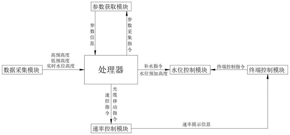
[0005] In order to overcome the above-mentioned technical problems, the purpose of the present invention is to provide a multi-water tank water level monitoring and analysis system based on big data: the optical cable cooling information is collected through the data acquisition module, and then according to the minimum height of the optical cable in the water tank and the inner cavity of the optical cable cooling water tank The top height obtains the preset height of the water level, so that the real-time water level controlled by the water level control module is within the preset height of the water level, thereby ensuring that the optical cable can continuously cool down and achieve a good cooling effect. After the parameter acquisition module collects the parameters, the parameters are processed The real-time water level is controlled by the water level control module to continuously rise, ensuring sufficient water in the water tank, and solving the problem of insufficient water in the existing water tank, which may easily cause the temperature of the optical cable to fail to drop, which will affect the final quality of the finished product. Adding cooling water inside can have a good cooling effect, but it will cause a serious waste of water resources

Method used


Image

  • Multi-water-tank water level monitoring and analyzing system based on big data

Examples


Embodiment 1

[0040] see figure 1 As shown, the present embodiment is a multi-sink water level monitoring and analysis system based on big data, including a data acquisition module, a processor, a parameter acquisition module and a water level control module;

[0041] The data acquisition module is used to collect the optical cable cooling information, the preset water level information, the real-time water level in the optical cable cooling water tank and send it to the processor. The optical cable cooling information includes the minimum height of the optical cable in the water tank and the inner cavity of the optical cable cooling water tank Top height, water level preset height information includes low preset height and high preset height, the specific process is as follows:

[0042] The data acquisition module collects the lowest height of the optical cable in the water tank and the top height of the inner cavity of the optical cable cooling water tank. The preset value above the lowes...

Embodiment 2

[0057] see figure 1 As shown, this embodiment is a multi-water tank water level monitoring and analysis system based on big data, which also includes a rate control module and a terminal control module;

[0058] The rate control module is used to control the moving rate of the optical cable, and the specific process is as follows:

[0059] When the speed control module receives the optical cable movement instruction, it controls the movement speed of the optical cable to be equal to the preset movement speed Vc;

[0060] After the processor receives the departure temperature W1, it compares the departure temperature W1 with the preset cooling temperature range of the optical cable, marks the upper limit of the preset cooling temperature range of the optical cable as Wmax, and marks the lower limit of the preset cooling temperature range of the optical cable as Wmin;

[0061] like (Wmin, Wmax), the processor generates a speed control instruction, and the processor sends the ...

Embodiment 3

[0067] see figure 1 As shown, in combination with Embodiment 1 and Embodiment 2, this embodiment is a working process of a multi-sink water level monitoring and analysis system based on big data, including the following steps:

[0068] Step 1: The data acquisition module collects the lowest height of the optical cable in the water tank and the top height of the inner cavity of the optical cable cooling water tank. 5cm is set as the high pre-height Hmax, the data acquisition module includes several water level sensors, and several water level sensors are respectively installed in the cavity of several optical cable cooling water tanks, and the data acquisition module uses the water level sensor to collect the real-time water level height Hs in the optical cable cooling water tank , the data acquisition module sends the low pre-height Hmin, the high pre-height Hmax and the real-time water level Hs to the processor;

[0069] Step 2: After the processor receives the low pre-heigh...


PUM


Abstract

The invention relates to the field of optical cable production, and aims to solve the problems that the final quality of a finished product is affected due to the fact that water in an existing water tank is insufficient and the temperature of an optical cable cannot be reduced easily, and serious waste of water resources can be caused if a good cooling effect can be achieved if cooling water is continuously added into a cold water tank. The system comprises a data acquisition module, a processor, a parameter acquisition module, a rate control module, a water level control module and a terminal control module, the system controls the real-time water level height to continuously rise through the water level control module, and it is guaranteed that water in water tanks is sufficient; the temperature of the optical cable can be reduced, the final quality of a finished product is guaranteed, the water level in the water tank is increased in real time, the cooling effect can still be guaranteed when the water amount is small, and a large amount of cooling water is not used, so that water resource loss is reduced.

Description

technical field [0001] The invention relates to the field of optical cable production, specifically designs the field of water level monitoring of multiple optical cable cooling water tanks, and specifically relates to a multi-water tank water level monitoring and analysis system based on big data. Background technique [0002] During the production process of the optical cable, the bare optical fiber should be protected, and the optical fiber can be protected and dyed by wrapping the optical fiber with PVC plastic. Due to the high temperature of the extruded PVC plastic at the beginning, in order to cool it quickly, the wrapped optical fiber is cooled by the water tank, and then the water is blown off by the blower, and the wire is typed into a coil, and the temperature of the water tank is lowered. An important link, the current cooling water tank is composed of a rectangular parallelepiped tank body. Guide rollers are respectively arranged at both ends of the tank cavity....

Claims


Application Information

Patent Timeline
IPC IPC(8): G01F23/80
Inventor 郝玉磊陈伟杨标弓晓明宋良芬牛玉双
Owner 安徽天凯光通信技术有限公司
Learn More