
Spring machine

A technology of spring machine and machine base, which is applied in the field of spring machine and can solve problems such as the inability to produce high-precision tiny springs

Pending Publication Date: 2020-12-04
SUZHOU PROTEC AUTO-CONTROL TECH CO LTD
View PDF0 Cites 0 Cited by
  • Summary
  • Abstract
  • Description
  • Claims
  • Application Information

AI Technical Summary

Problems solved by technology

In the prior art, the spring machine cannot produce high-precision tiny springs

Method used


Image

  • Spring machine
  • Spring machine
  • Spring machine

Examples


Embodiment Construction

[0017] The preferred embodiments of the present invention will be described in detail below in conjunction with the accompanying drawings, so that the advantages and features of the present invention can be more easily understood by those skilled in the art, so as to define the protection scope of the present invention more clearly.

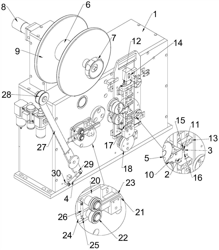
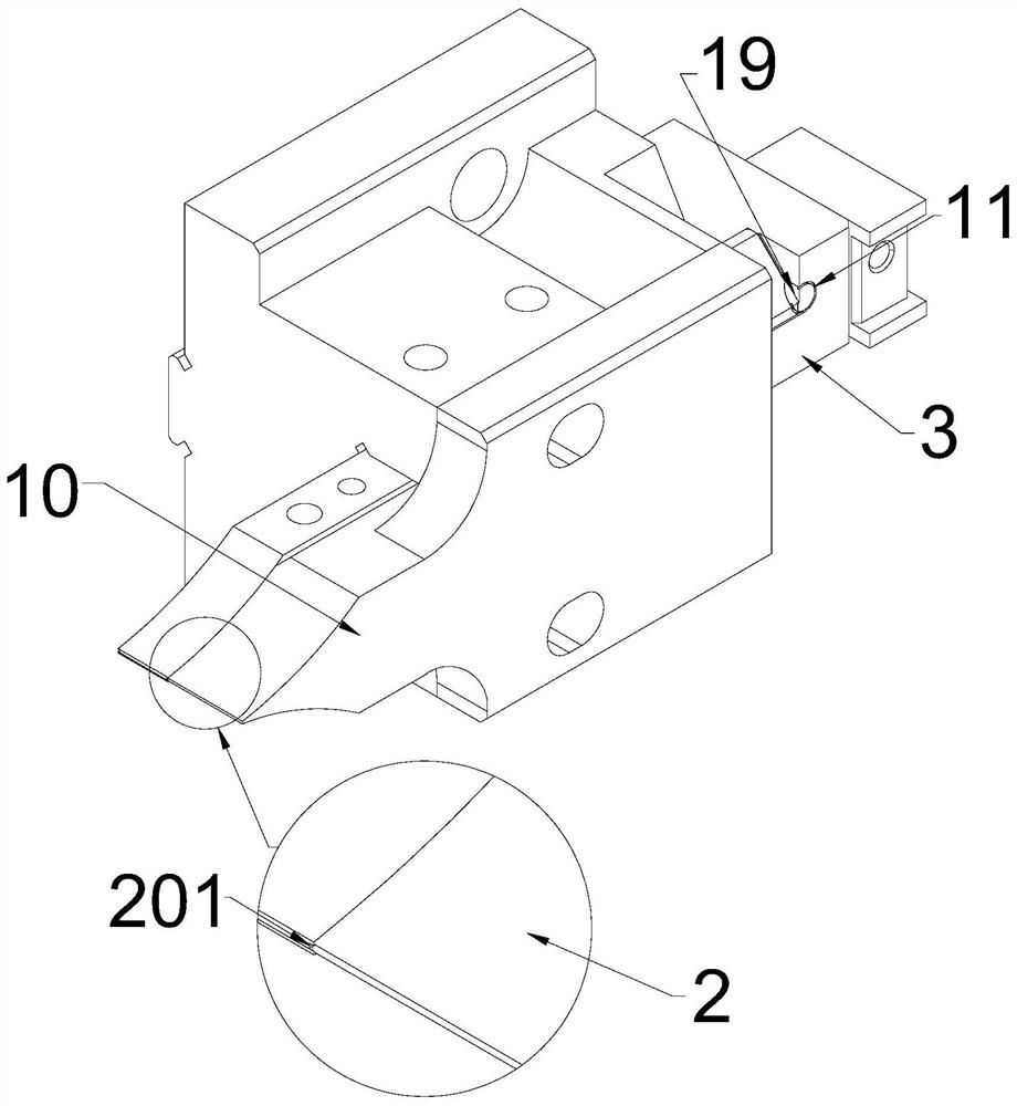
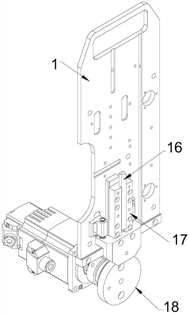
[0018] See attached Figure 1-3 Shown, a kind of spring machine comprises machine base 1, and machine base 1 is provided with feeding mechanism, feeding mechanism and forming material cutting mechanism, and feeding mechanism includes feeding rotating shaft 6, rotating handle 7, feeding motor 8 and a For the feeding limit plate 9, the feeding motor 8 is arranged on the machine base 1 and the output shaft passes through the machine base 1 and is connected to the feeding rotating shaft 6. The material rotating shaft 6 is surrounded by a steel wire, and two feeding limiting plates 9 are arranged in parallel on the feeding rotating shaft 6 and located...


PUM


Abstract

The invention discloses a spring machine which comprises a machine base. A feeding mechanism, a feeding mechanism and a forming and cutting mechanism are arranged on the machine base, the feeding mechanism is located on one side of the forming and cutting mechanism, an equal-diameter mechanism is further arranged on the machine base, and the equal-diameter mechanism is located between the feedingmechanism and the forming and cutting mechanism. The feeding mechanism comprises a pair of feeding rollers driven by a feeding motor, a certain distance is reserved between the two feeding rollers toform a steel wire feeding channel, the equal-diameter mechanism comprises a forming die and a forming pressing plate, a feeding pressing nozzle is arranged at one end of the forming die, and the end of the feeding pressing nozzle is located in the steel wire feeding channel. A steel wire passing hole is formed in the forming die in the length direction, a spring forming rail is arranged on the forming pressing plate, and the two ends of the steel wire passing hole communicate with the interior of the steel wire feeding channel and the spring forming rail respectively. The structure is simple,and production and machining of high-precision micro springs can be achieved.

Description

technical field [0001] The invention relates to the field of spring production equipment, in particular to a spring machine. Background technique [0002] Spring is a necessary accessory in many devices, and it is widely used in many devices, including objects, to achieve the effects of shock absorption and recovery. Spring machine refers to the mechanical equipment for producing springs. According to the functional characteristics, it is divided into: compression spring machine, extension spring machine, universal machine, disc machine and special spring machine. In the prior art, spring machines cannot produce high-precision tiny springs. Contents of the invention [0003] In order to overcome the above-mentioned shortcomings, the object of the present invention is to provide a spring machine with simple structure and capable of realizing the production and processing of high-precision tiny springs. [0004] In order to achieve the above purpose, the technical solution...

Claims


Application Information

Patent Timeline
IPC IPC(8): B21F35/00B21F1/02B21F23/00B21F11/00B21C51/00
CPCB21C51/00B21F1/02B21F11/005B21F23/00B21F35/00
Inventor 李向阳陈见樊连杰
Owner SUZHOU PROTEC AUTO-CONTROL TECH CO LTD
Learn More