Indoor skid-mounted type polyurethane spraying polyethylene winding thermal-insulation tube production line

A polyethylene and polyurethane technology, applied in the field of thermal insulation pipe production equipment, can solve the problems of large space occupation, scattered production line layout, low production line applicability, etc., and achieves the effect of compact layout, increased applicability, and reduced space occupation

Pending Publication Date: 2018-12-07
奥菲德(天津)管道科技有限公司
View PDF0 Cites 0 Cited by
  • Summary
  • Abstract
  • Description
  • Claims
  • Application Information

AI Technical Summary

Problems solved by technology

[0003] 1. The layout of the production line is scattered and takes up a lot of space
[0004] 2. In the production process of polyurethane insulation pipe

Method used


Image

  • Indoor skid-mounted type polyurethane spraying polyethylene winding thermal-insulation tube production line
  • Indoor skid-mounted type polyurethane spraying polyethylene winding thermal-insulation tube production line
  • Indoor skid-mounted type polyurethane spraying polyethylene winding thermal-insulation tube production line

Examples


Embodiment 1

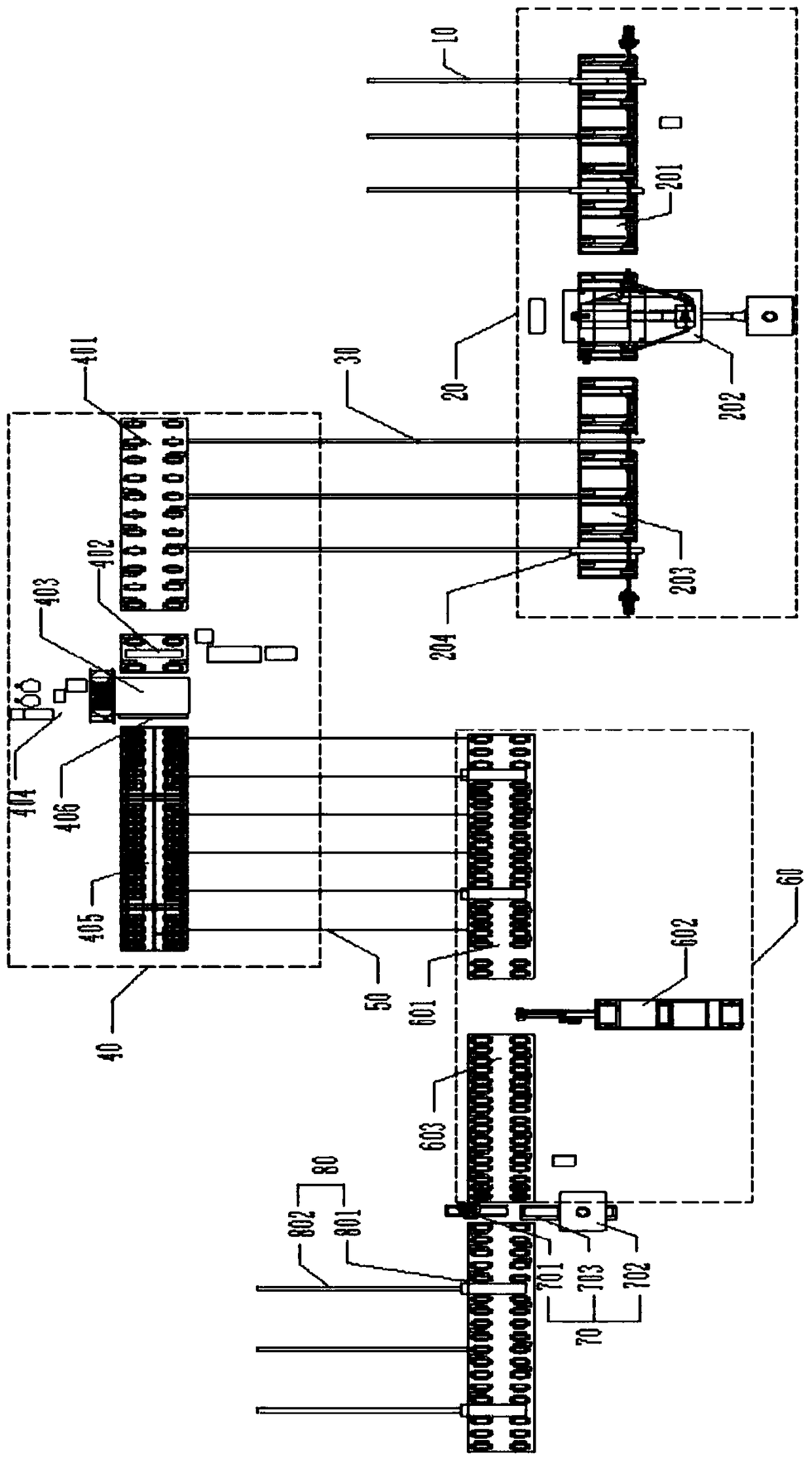
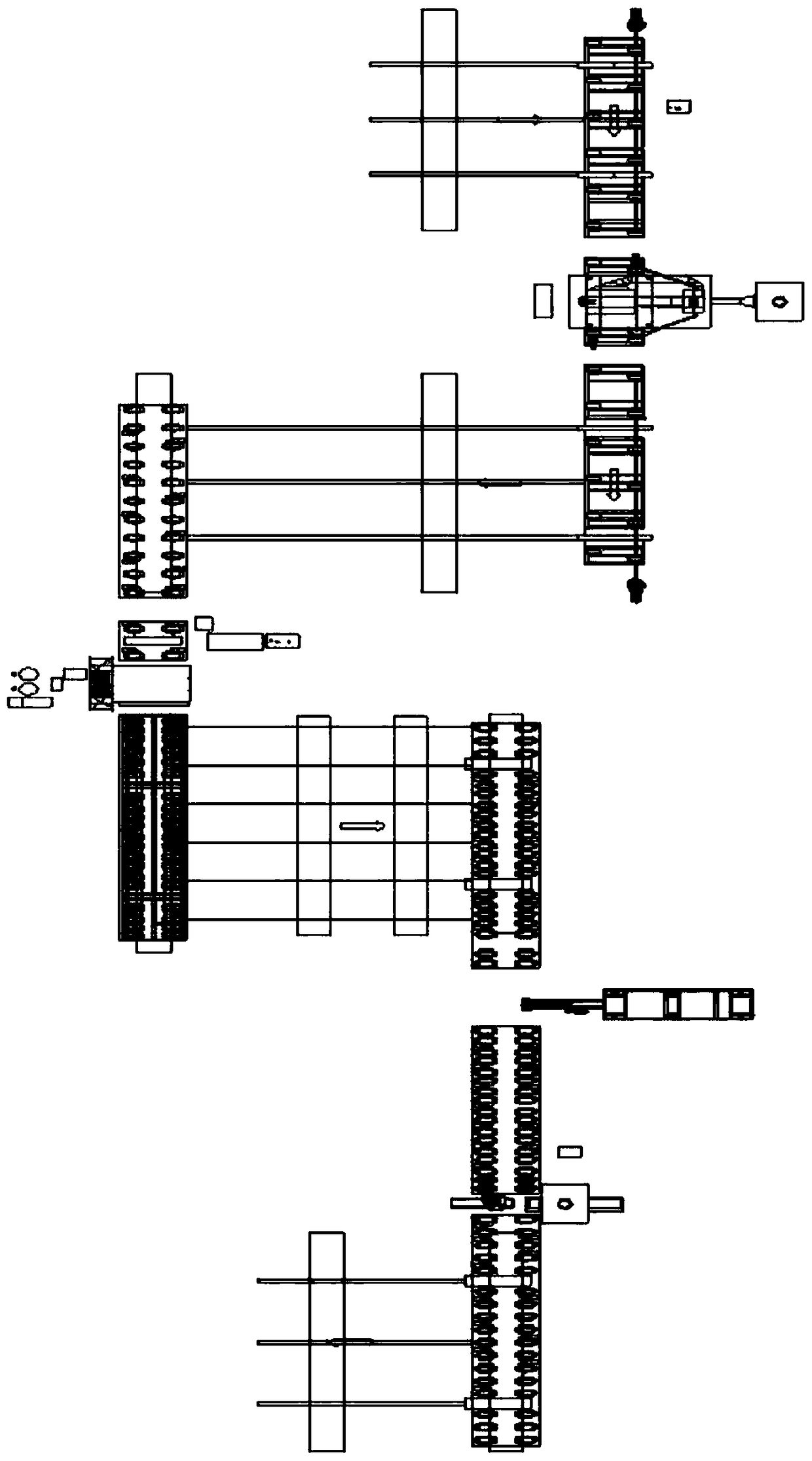
[0031] Embodiment 1: as figure 1 , figure 2 , Figure 7 and Figure 8 As shown, the indoor skid-mounted polyurethane spraying polyethylene winding insulation pipe production line includes upper pipe platform one 10, steel pipe rust removal part 20, upper pipe platform two 30, polyurethane spraying part 40, upper pipe platform three 50, polyethylene winding part 60. The cutting part 70 and the finished product storage part 80, the output end of the upper pipe platform one 10 is connected to the input end of the steel pipe derusting part 20, and the output end of the steel pipe derusting part 20 is connected to the input of the polyurethane spraying part 40 through the upper pipe platform two 30 end, the output end of the polyurethane spraying part 40 is connected to the input end of the polyethylene winding part 60 through the upper pipe platform three 50, and the output end of the polyethylene winding part 60 is connected to the input end of the finished product storage par...

Embodiment 2

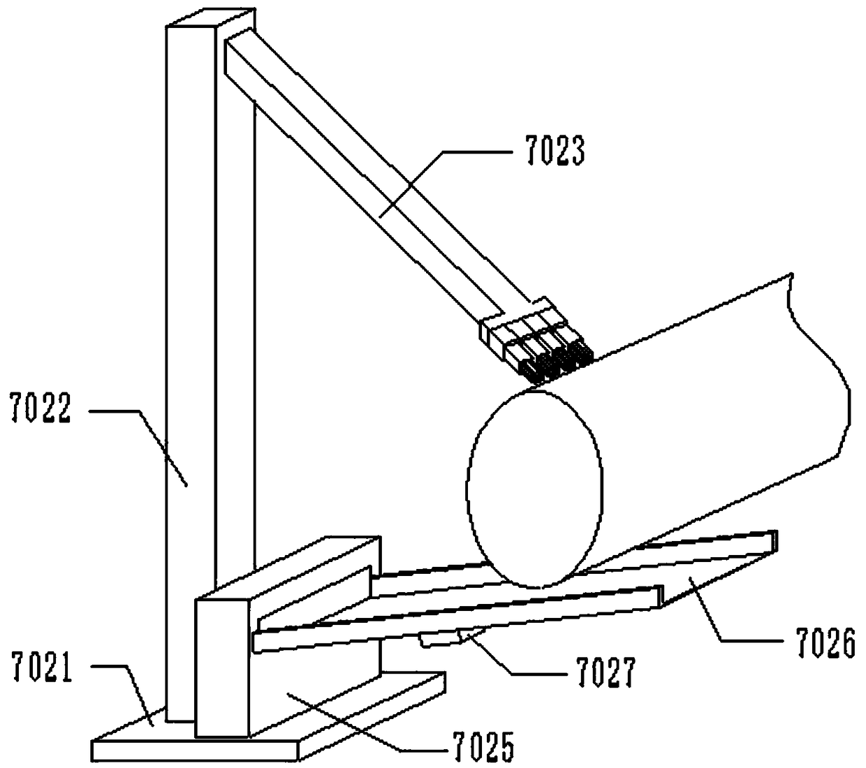
[0038] Embodiment 2: The difference with Embodiment 1 is that, as figure 1 , Figure 5 and Figure 6 As shown, further, the cutting part 70 is configured to include a cutting saw 701 and a dust removal device 702, the cutting saw 701 is arranged between the polyethylene winding part 60 and the finished product storage part 80, the dust removal device 702 is arranged correspondingly to the cutting saw 701, and The bottoms of the cutting saw 701 and the dust removal device 702 are all provided with a longitudinal adjustment mechanism 703, through the setting of the longitudinal adjustment mechanism 703, the adjustment of the distance between the cutting saw 701 and the dust removal device 702 and the heat preservation pipe to be cut can be realized, so that the cutting saw 701 701 and dust removal device 702 can meet the needs of good treatment of insulation pipes of different specifications, thereby increasing the applicability of the production line.

[0039] Further, the lo...

Embodiment 3

[0041] Embodiment 3: The difference with Embodiment 1 and 2 is that, as Figure 5 and Figure 6 As shown, further, a guide rail protection cover is provided on the two sets of guide rails 7036 in cooperation with each other. The guide rail protection cover is set to be composed of multiple sets of sliding sleeves 7037 that are sequentially slidably connected, and the top wall of the last set of sliding sleeves 7037 is fixed with a mounting base 7032 , the inner surface of the top wall of each set of sliding sleeves 7037 is provided with a sliding groove 7038, and the end of the outer surface of the top wall of the sliding sleeve 7037 is provided with a slider 7039, the structure of the sliding block 7039 matches the structure of the sliding groove 7038, wherein The first set of sliding sleeves 7037 is welded and fixed on the guide rail 7036. When the mounting base 7032 moves longitudinally along the guide rail 7036 with the drive motor 7033, gear 7034 and rack 7035, the slide ...


PUM


Abstract

The invention provides an indoor skid-mounted type polyurethane spraying polyethylene winding thermal-insulation tube production line. The indoor skid-mounted type polyurethane spraying polyethylene winding thermal-insulation tube production line comprises a tube loading platform I, a steel tube rust-removal part, a tube loading platform II, a polyurethane spraying part, a tube loading platform III, a polyurethane winding part, a cutting part and a finished product storage part, wherein the output end of the tube loading platform I is connected with the input end of the steel tube rust-removalpart; the output end of the steel tube rust-removal part is connected with the input end of the polyurethane spraying part through the tube loading platform II; the output end of the polyurethane spraying part is connected with the input end of the polyurethane winding part through the tube loading platform III; the cutting part is arranged between the polyurethane winding part and the finished product storage part; and the steel tube rust-removal part, the polyurethane spraying part and the polyurethane winding part are arranged in the form of an inverted U. The production line adopted by the invention is compact in structure, is relatively small in space usage, can meet good cutting treatment of thermal-insulation tubes of different specifications, and is relatively high in applicability.

Description

technical field [0001] The invention relates to the technical field of insulation pipe production equipment, in particular to an indoor skid-mounted polyurethane spray-coated polyethylene winding insulation pipe production line. Background technique [0002] Polyurethane sprayed polyethylene winding insulation pipe is mainly used for the transportation of liquid, gas and other media. Therefore, it is widely used in thermal insulation projects of petroleum, chemical industry, aerospace, central heating, central air conditioning, municipal and other pipelines. However, the existing production line for polyurethane sprayed polyethylene winding insulation pipe has the following deficiencies in actual use: [0003] 1. The layout of the production line is scattered and takes up a lot of space. [0004] 2. In the production process of polyurethane insulation pipes, the good cutting treatment of insulation pipes of different specifications cannot be satisfied, which makes the appli...

Claims


Application Information

Patent Timeline
IPC IPC(8): B29D23/00
CPCB29D23/001
Inventor 李光远李楠
Owner 奥菲德(天津)管道科技有限公司
Why Eureka
Try Eureka