A multi-degree-of-freedom circuit board CNC machining machine tool

A technology for CNC machining machine tools and circuit boards, which is applied in the direction of metal processing machinery parts, metal processing equipment, manufacturing tools, etc., can solve the problems that circuit boards cannot be processed at the same time, and achieve convenient installation and connection, high degree of automation, The effect of rapid processing

Active Publication Date: 2021-12-17
深圳市爱迅通信设备有限公司
View PDF6 Cites 0 Cited by
  • Summary
  • Abstract
  • Description
  • Claims
  • Application Information

AI Technical Summary

Problems solved by technology

However, this equipment cannot process the wiring grooves on both sides of the circuit board at the same time

Method used


Image

  • A multi-degree-of-freedom circuit board CNC machining machine tool
  • A multi-degree-of-freedom circuit board CNC machining machine tool
  • A multi-degree-of-freedom circuit board CNC machining machine tool

Examples


specific Embodiment approach 1

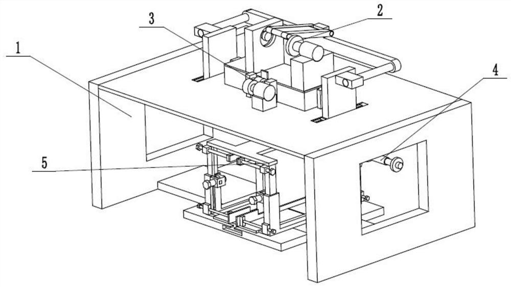
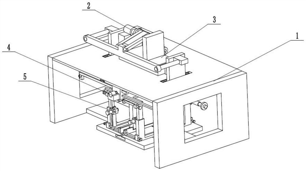
[0029] Such as Figure 1 to Figure 10 As shown, a multi-degree-of-freedom circuit board CNC processing machine tool includes a processing frame 1, a front and rear plane displacement driver 2, a longitudinal displacement driver 3, a symmetrical circuit board wiring groove processor 4 and a circuit board processing clamp 5, The front and rear planar displacement drivers are slidingly connected to the processing frame 1, the front and rear planar displacement drivers 2 are fixedly connected to the longitudinal displacement driver 3, and the longitudinal displacement driver 3 is longitudinally slidably connected to the processing frame 1, and the symmetrical circuit board wiring The two ends of the groove processor 4 are respectively connected to the front and rear plane displacement drivers 2 through the rotation of the sphere, the upper end of the symmetrical circuit board wiring groove processor 4 is slidably connected to the processing frame 1, and the circuit board processing...

specific Embodiment approach 2

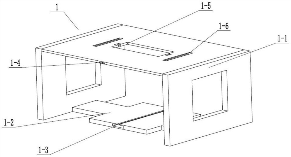
[0030] Such as Figure 1 to Figure 10 As shown, this embodiment will further illustrate Embodiment 1. The processing frame 1 includes a frame frame 1-1, a processing frame sliding bottom plate 1-2, a lower T-shaped chute 1-3, an upper T-shaped chute 1-4, the central longitudinal channel 1-5 and two slider chute 1-6, the sliding bottom plate 1-2 of the processing frame is fixedly connected to the lower end of the inner wall of the frame frame 1-1, and the lower T-shaped chute 1-3 The front and back are set on the sliding bottom plate 1-2 of the processing frame, the upper T-shaped chute 1-4 is set on the upper end of the inner wall of the frame frame 1-1, and the central longitudinal channel 1-5 is vertically penetrated and set on the frame frame 1-1 The upper end of the frame frame 1-1, two slide block chute 1-6 is evenly arranged on the upper end of the frame frame 1-1. The two ends of the frame frame 1-1 are respectively provided with two operation frames, which are conveni...

specific Embodiment approach 3

[0031] Such as Figure 1 to Figure 10 As shown, this embodiment will further explain the second embodiment. The front and rear plane displacement driver 2 includes a motor base 2-1, a front and rear translation drive servo motor 2-2, a drive turntable 2-3, and a drive slide bar 2-4. , limit turning slot 2-5, turning slot fixing seat 2-6, driving hinge plate 2-7, hinge seat 2-8, translation connecting rod 2-9 and two connecting sub-rods 2-10, front and rear translation drive servo The motor 2-2 is fixedly connected to the motor base 2-1, the drive turntable 2-3 is fixedly connected to the transmission shaft of the front and rear translation drive servo motor 2-2, and one end of the drive slide bar 2-4 is fixedly connected to the drive turntable 2- 3, the other end of the driving slide bar 2-4 is slidably connected in the limit turning groove 2-5, the limit turning groove 2-5 is arranged on the turning groove fixing seat 2-6, and the drive hinge plate 2-7 The two ends of the dr...


PUM


Abstract

The invention relates to the field of machine tool processing, more specifically a multi-degree-of-freedom circuit board CNC processing machine tool, including a processing frame, a front and rear plane displacement driver, a longitudinal displacement driver, a symmetrical circuit board cable groove processor and a circuit board processing machine Clamp, the front and rear planar displacement drivers are slidingly connected to the processing frame, the front and rear planar displacement drivers are fixedly connected to the longitudinal displacement driver, the longitudinal displacement driver is longitudinally slid and connected to the processing frame, and the symmetrical circuit board wiring groove The two ends of the processor are respectively connected in the front and rear plane displacement drivers through the rotation of the sphere; the beneficial effect of the present invention is that symmetrical wiring slots can be processed on both ends of the circuit board at the same time, which facilitates the installation and connection of electrical components on the circuit board; The processing freedom is high, and the processing angle and depth can be adjusted according to different needs; the degree of automation is high, and the circuit boards can be automatically processed in batches and quickly.

Description

technical field [0001] The invention relates to the field of machine tool processing, in particular to a circuit board numerical control processing machine tool with multiple degrees of freedom. Background technique [0002] The patent number is CN201910725106.0, which discloses a multi-degree-of-freedom circuit board CNC processing machine tool, including a machine base and a processing platform detachably installed on the machine base, and the top of one side of the machine base is fixedly installed for A hydraulic telescopic cylinder that pushes the drilling assembly to move up and down. The top of the piston rod of the hydraulic telescopic cylinder is fixed with a lifting seat, and one side of the lifting seat is fixed with a vertical fixing seat directly above the support groove; A hollow rotating cylinder is provided to penetrate and rotate into the fixed seat, and the bottom end of the hollow rotating cylinder is fixedly installed with a supporting turntable, and the ...

Claims


Application Information

Patent Timeline
Patent Type & Authority Patents(China)
IPC IPC(8): B23B41/00B23B47/20B23Q3/06
CPCB23B41/00B23Q5/28B23Q3/06
Inventor 陈远旭
Owner 深圳市爱迅通信设备有限公司
Why Eureka
Try Eureka