Manifold welding machine

A welding machine and manifold technology, used in welding equipment, welding equipment, auxiliary welding equipment, etc., can solve the problems of uncertain connection speed, decreased welding seam strength, large impact, etc., to achieve automatic welding and uniform welding seam. Smooth, lower product cost effect

Pending Publication Date: 2020-12-04
NINGBO HENGSHUAI CO LTD
View PDF0 Cites 2 Cited by
  • Summary
  • Abstract
  • Description
  • Claims
  • Application Information

AI Technical Summary

Problems solved by technology

[0004] 1. The joining speed of the upper part of the manifold and the lower part of the manifold is random and uncertain, so that the melting surface of the upper part of the manifold and the lower part of the manifold may have a greater impact when they are butted together, and most of the molten material will be squeezed out to the On both sides of the welding surface, some incompletely melted materials will participate in mutual fusion, which will lead to incomplete fusion and solidification of the joint surface, and at the same time, a large impact will cause slippage and dislocation of the inclined surface, which will reduce the strength of the weld seam
[0005] 2. When the manifold is solidified, the final positions of the upper part of the manifold and the lower part of the manifold are uncertain, and will be affected by the product height tolerance of the upper part of the manifold and the lower part of the manifold and the fluctuation of the depth of the molten layer on the melting surface, which will cause changes in the height of the weld seam, thus Affects weld strength

Method used


Image

  • Manifold welding machine
  • Manifold welding machine
  • Manifold welding machine

Examples


Embodiment Construction

[0043] The present invention will be further described below in conjunction with accompanying drawings and embodiments.

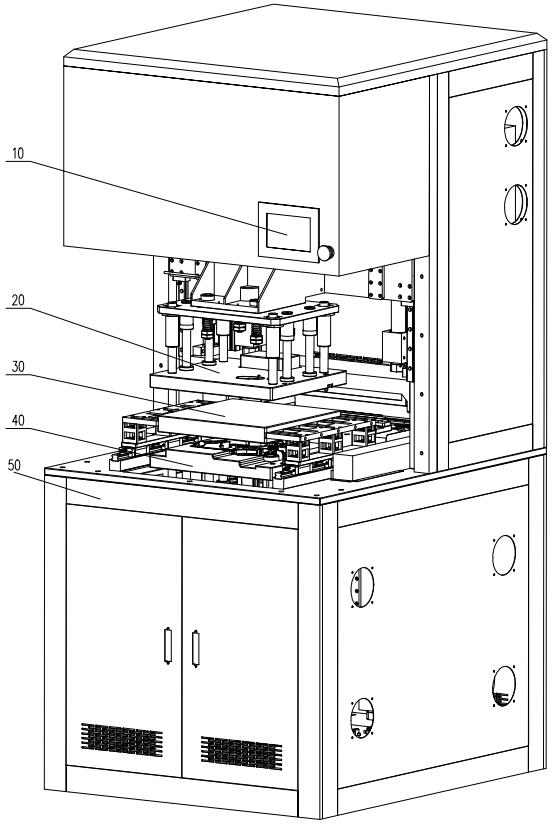
[0044] Such as Figure 1-11 As shown, a manifold welding machine includes a control system 10 , a driving and positioning mechanism 20 for the upper part of the manifold, a driving mechanism 30 for the hot melt plate, a driving and positioning mechanism 40 for the lower part of the manifold, and a frame 50 .

[0045] The control system 10 , the upper manifold driving and positioning mechanism 20 , the hot melt plate driving mechanism 30 , and the manifold lower driving and positioning mechanism 40 are all arranged on the frame 50 .

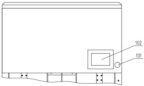
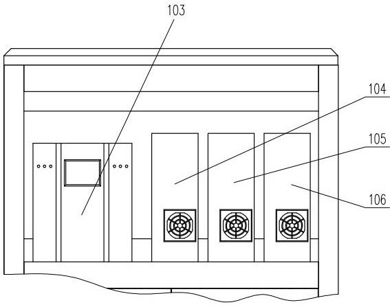
[0046] Such as figure 2 , 3 As shown, the above-mentioned control system 10 includes an emergency button 101, an operation display screen 102, a PLC controller 103, a servo motor driver 104 on the upper part of the manifold, a servo motor driver 105 on the hot melt plate and a servo motor driver 106 on the lower part of the ...


PUM


Abstract

The invention relates to a manifold welding machine. The manifold welding machine comprises a manifold upper portion driving and positioning mechanism, a hot melting plate driving mechanism, a manifold lower portion driving and positioning mechanism and a control system, wherein the control system controls the hot melting plate driving mechanism to move forwards to a working position; the upper driving and positioning mechanism and the lower driving and positioning mechanism move downwards and upwards respectively, welding surfaces of the upper portion and the lower portion of a manifold are attached to a hot melting plate for being heated, and heating melting of the welding surfaces is completed; the upper driving and positioning mechanism and the lower driving and positioning mechanism continue to move downwards and upwards respectively to attach the two hot melting surfaces of the upper portion and the lower portion of the manifold together; when the two hot melting surfaces of theupper portion and the lower portion of the manifold begin to be attached to each other and in contact with each other, an upper pressure sensor and a lower pressure sensor sense pressure increase andtransmit the pressure increase to the control system, and the control system immediately reduces the running speed of the manifold upper portion driving and positioning mechanism and the manifold lower portion driving and positioning mechanism; and when the pressure sensed by the pressure sensors is increased to a set maximum value, the welding surfaces begin to be cooled until the welding surfaces are completely cured.

Description

technical field [0001] The invention relates to a manifold welding machine. Background technique [0002] Manifold is a common part of the car, which is usually produced separately into the upper part of the manifold and the lower part of the manifold, and then the two are welded together. [0003] Existing manifold 6 welding mostly adopts hot plate welding, because there are many welding surfaces 623 on the upper part 61 of the manifold and the lower part of the manifold 62, and there are various types of welding surfaces such as plane 621 and inclined plane 622, see Figure 10 , which mainly has the following deficiencies: [0004] 1. The joining speed of the upper part of the manifold and the lower part of the manifold is random and uncertain, so that the melting surface of the upper part of the manifold and the lower part of the manifold may have a greater impact when they are butted together, and most of the molten material will be squeezed out to the On both sides of...

Claims


Application Information

Patent Timeline
Patent Type & Authority Applications(China)
IPC IPC(8): B23K31/02B23K37/04
CPCB23K31/02B23K37/0443
Inventor 王烈邵淇许宁宁刘培海
Owner NINGBO HENGSHUAI CO LTD
Why Eureka
Try Eureka