Paper tube manufacturing system

A manufacturing system and paper tube technology, applied in the field of paper product manufacturing, can solve the problems of twisting the surface of the belt, economic losses for users, increase the scrap rate, etc., to prevent accumulation and jam, improve processing quality, and improve product quality.

Inactive Publication Date: 2020-12-04
太仓天诚包装制品有限公司
View PDF8 Cites 0 Cited by
  • Summary
  • Abstract
  • Description
  • Claims
  • Application Information

AI Technical Summary

Problems solved by technology

The existing coiling device is vertically provided with belt rollers on both sides. By winding the belt on the paper tube and the belt roller, the belt rollers on both sides will drive the paper tube to move along the axial direction when the belt rollers move, and then when the paper tube is wound, Push the rolled paper tube away from the winding area; but when pushing the paper tube, the belt is wound on the vertically arranged belt roller and the horizontally moving paper tube, and the surface of the belt will inevitably be twisted during winding, so that the belt is pushed There will be too much friction between the paper tube and the paper tube, which will easily cause the surface of the rolled paper tube to wear, increase the scrap rate, affect the appearance, and bring economic losses to the user

Method used


Image

  • Paper tube manufacturing system
  • Paper tube manufacturing system
  • Paper tube manufacturing system

Examples


Embodiment Construction

[0047] In order to explain the overall concept of the present invention more clearly, the following will be described in detail by way of examples in conjunction with the accompanying drawings.

[0048] In describing the present invention, it is to be understood that the terms "center", "upper", "lower", "front", "rear", "left", "right", "vertical", "horizontal", The orientation or positional relationship indicated by "top", "bottom", "inner", "outer", "axial", "radial" and "circumferential" are based on the orientation or positional relationship shown in the drawings, only It is for the convenience of describing the present invention and simplifying the description, but does not indicate or imply that the referred device or element must have a specific orientation, be constructed and operated in a specific orientation, and thus should not be construed as limiting the present invention.

[0049] In addition, the terms "first" and "second" are used for descriptive purposes only...


PUM


Abstract

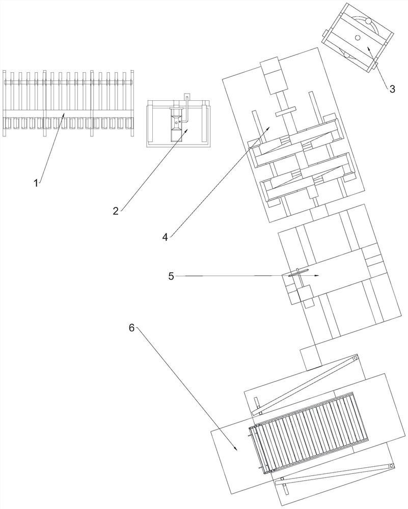
The invention discloses a paper tube manufacturing system. The paper tube manufacturing system comprises a body paper unwinding mechanism, a gluing mechanism, a paper film unwinding mechanism, a tubewinding mechanism, a tube cutting mechanism and a collecting mechanism, and the body paper unwinding mechanism is used for unwinding body paper; the gluing mechanism is arranged on one side of a bodypaper unwinding frame and used for gluing the unwound body paper; the paper film unwinding mechanism is arranged on the side, away from the body paper unwinding frame, of the gluing mechanism and usedfor unwinding a paper film; the tube winding mechanism is arranged between the gluing mechanism and a paper film unwinding frame and comprises a tube winding assembly and a tube pushing assembly, thetube winding assembly is used for winding tubes, and the tube pushing assembly is used for pushing the paper tubes wound by the tube winding assembly; the tube cutting mechanism is arranged on the downstream side of the tube winding mechanism in the paper tube pushing direction and used for cutting off wound paper tubes during tube winding of the tube winding assembly; and the collecting mechanism is arranged on the side, away from the tube winding mechanism, of a cutter assembly and used for collecting the paper tubes cut off by the cutter assembly.

Description

technical field [0001] The invention belongs to the technical field of paper product manufacturing, and in particular relates to a paper tube manufacturing system. Background technique [0002] Paper tubes are commonly used items in daily life, such as toilet paper rolls, paper tubes, salute tubes, plastic wrap tubes, etc., and are widely used in many fields. The existing coiling device is vertically provided with belt rollers on both sides. By winding the belt on the paper tube and the belt roller, the belt rollers on both sides will drive the paper tube to move along the axial direction when the belt rollers move, and then when the paper tube is wound, Push the rolled paper tube away from the winding area; but when pushing the paper tube, the belt is wound on the vertically arranged belt roller and the horizontally moving paper tube, and the surface of the belt will inevitably be twisted during winding, so that the belt is pushed There will be too much friction between th...

Claims


Application Information

Patent Timeline
IPC IPC(8): B31C11/00B31C11/04
CPCB31C11/00B31C11/04
Inventor 许修平
Owner 太仓天诚包装制品有限公司
Why Eureka
Try Eureka