Textile fabric rapid automatic cutting device
A textile cloth and cutting device technology, applied in the field of textile cloth, can solve the problems that the cutting size cannot be changed, and the use range is single, so as to achieve the effect of wide use range and avoid accumulation
- Summary
- Abstract
- Description
- Claims
- Application Information
AI Technical Summary
Problems solved by technology
Method used
Image
Examples
Embodiment 1
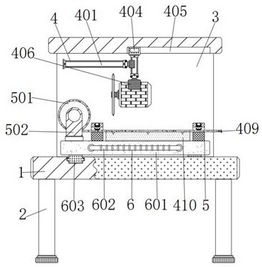
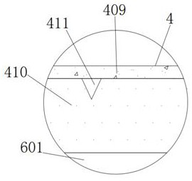
[0031]A rapid automatic cutting device for textile fabrics, comprising a base plate 1, the middle of the top of the base plate 1 is fixedly connected with the bottom end of a first support plate 3, a cutting mechanism 4 is installed on the upper inner side of the first support plate 3, and the cutting mechanism 4 includes a first Hydraulic cylinder 401, first splint 402, second hydraulic cylinder 403, first slider 404, first chute 405, second splint 406, motor 407, cutter 408, textile fabric 409, rubber pad 410 and knife groove 411 , the left rear end of the first hydraulic cylinder 401 is fixedly connected with the upper left rear end surface of the first support plate 3, the right output end of the first hydraulic cylinder 401 is fixedly connected with the middle of the left end of the first splint 402, and the first splint The right side of 402 is provided with the second hydraulic cylinder 403, the right inner wall of the first splint 402 is fixedly connected with the upper...
Embodiment 2
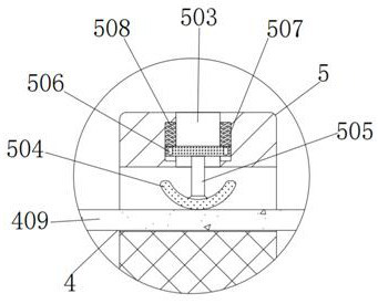
[0033] As an option, see figure 1 and 2 , textile cloth fast automatic cutting device, the left side of textile cloth 409 is equipped with fixed mechanism 5, and fixed mechanism 5 comprises cylinder 501, second support plate 502, concave plate 503, clip 504, vertical rod 505, second slide block 506 , the second chute 507, the compression spring 508, the outer wall of the drum 501 is wound and connected with textile cloth 409, the outer walls of the front and rear sides of the drum 501 are connected to the upper middle inner wall of the second support plate 502 through internal bearings, and the drum 501 passes through the front and rear The internal bearings on both sides can rotate counterclockwise in the second support plate 502 to convey the textile cloth 409 to the right. The right side of the second support plate 502 is provided with a concave plate 503, and the bottom surface of the upper inner side of the concave plate 503 is in contact with the textile cloth. The bott...
Embodiment 3
[0036] As an option, see figure 1 , 3 And 4, the fast automatic cutting device for textile cloth, a sliding structure 6 is installed in the middle of the top of the bottom plate 1, the sliding mechanism 6 includes a horizontal plate 601, a handle 602, a third slider 603 and a third chute 604, and the top of the horizontal plate 601 is sequentially The second supporting plate 502, the concave plate 503 and the rubber pad 410 are fixedly connected, the middle front end of the horizontal plate 601 is fixedly connected with a handle 602, and the left and right sides of the bottom end of the horizontal plate 601 are fixedly connected with a third slide block 603. The sliders 603 are all slidingly engaged with the third chute 604, and the third chute 603 is set on the upper left and right inner walls of the bottom plate 1, and the handle 602 is dragged so that the horizontal plate 601 passes through the third sliders 603 on both sides of the bottom plate. The third chute 604 on bot...
PUM
 Abstract
Description
Claims
Application Information
 - R&D
- Intellectual Property
- Life Sciences
- Materials
- Tech Scout
- Unparalleled Data Quality
- Higher Quality Content
- 60% Fewer Hallucinations
Browse by: Latest US Patents, China's latest patents, Technical Efficacy Thesaurus, Application Domain, Technology Topic, Popular Technical Reports.
© 2025 PatSnap. All rights reserved.Legal|Privacy policy|Modern Slavery Act Transparency Statement|Sitemap|About US| Contact US: help@patsnap.com


