Pile-soil combined action supporting device and construction method thereof

A technology of joint action and support device, which is applied in excavation, infrastructure engineering, construction, etc., can solve the problem that the shear strength of the upper soil cannot be fully utilized, the advantages of the soil itself cannot be utilized, and the soil arch cannot be formed. effect and other problems, to achieve the effect of reducing the amount of uneven settlement and deformation, reducing the risk of landslides, and increasing the service life.

Inactive Publication Date: 2020-12-04
JIANGSU UNIV OF SCI & TECH
View PDF6 Cites 0 Cited by
  • Summary
  • Abstract
  • Description
  • Claims
  • Application Information

AI Technical Summary

Problems solved by technology

But the problem is that the distance between two retaining piles is too small, which will not only cause too large a safety reserve, but also fail to form a soil arch effect, and the shear strength of the upper soil itself cannot be fully utilized, resulting in a waste of resources
The Chinese patent with application number 201920468303.4 discloses a retaining wall that is easy to construct. Steel piles are vertically inserted into the soil, and a soil retaining board is vertically inserted between the two steel piles. The steel piles are supported by anchor rods to prevent tilting, but the problem is that : Neither the soil retaining board nor the steel pile has permeable holes. When it encounters rainy weather, the water in the upper soil cannot be discharged, resulting in an increase in soil weight and weight, which increases the risk of landslides
[0005] In general, the existing form of slope support by driving piles into the soil relies more on past experience for construction design. Although it can effectively control the tendency of slope landslides, it has caused a lot of damage to resources. Waste, failing to make use of the soil's own advantages

Method used


Image

  • Pile-soil combined action supporting device and construction method thereof
  • Pile-soil combined action supporting device and construction method thereof
  • Pile-soil combined action supporting device and construction method thereof

Examples


Embodiment Construction

[0029] The directions shown in the accompanying drawings are up, down, left, and right.

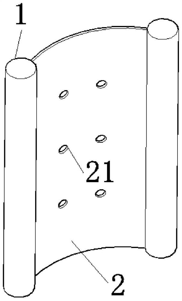
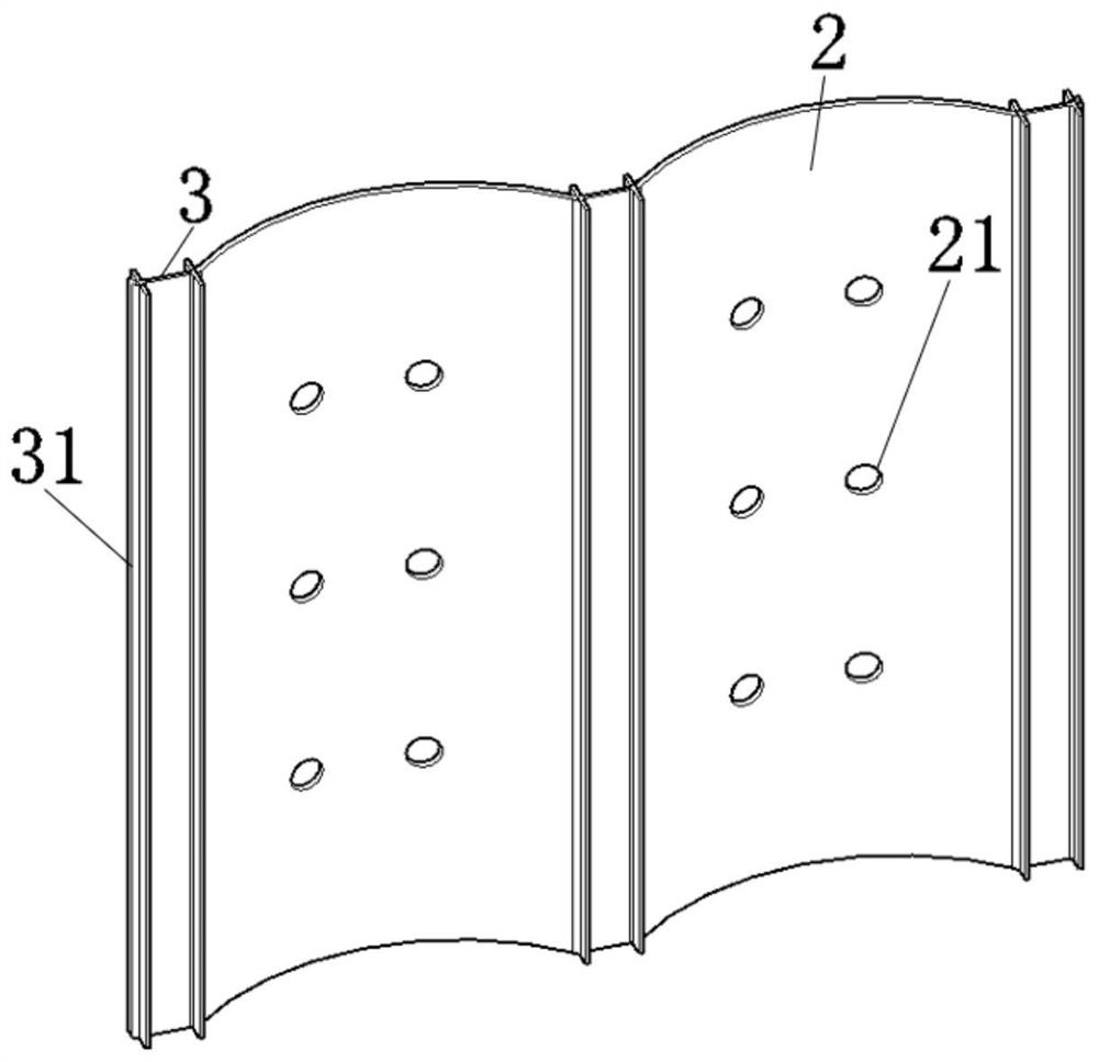
[0030] Such as Figure 1~2 The supporting device for pile-soil interaction includes bored cast-in-place pile 1 and steel plate 2, the bored cast-in-place pile 1 is inserted with H-shaped steel 3, and the steel plate 2 is an arc-shaped steel plate 2 that conforms to the radian of a reasonable arch axis in actual engineering. According to actual needs, a certain number of support devices are set up on the slope surface of the slope as needed.

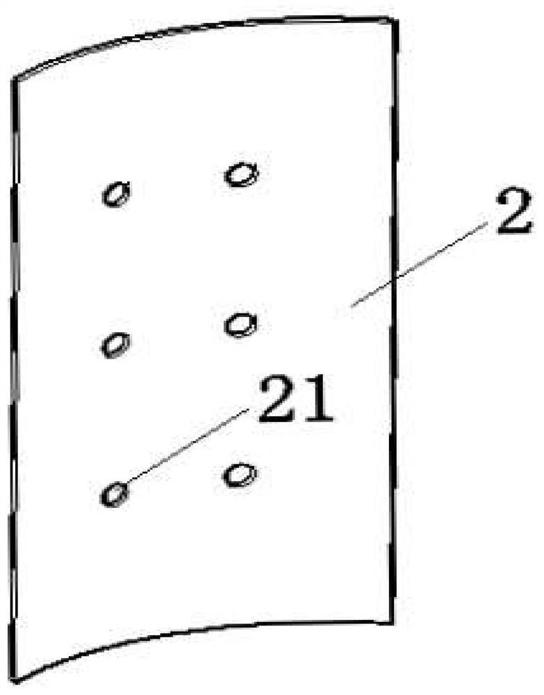
[0031] Such as image 3 The surface of the arc-shaped steel plate 2 has a through hole 21, the through hole 21 is circular, elliptical or any polygon, preferably circular, which is beneficial to soil drainage. The surface of the arc-shaped steel plate 2 has an anti-corrosion paint layer, and the anti-corrosion paint is existing. Bottom surfaces of the bored cast-in-place pile 1 and the steel plate 2 are lower than the sliding surface of the slope....


PUM


Abstract

The invention discloses a pile-soil combined action supporting device and a construction method thereof. The supporting device comprises cast-in-situ bored piles and steel plates which are connected with each other, wherein H-shaped steel is arranged in each cast-in-situ bored pile; through holes are formed in each steel plate; and the bottom surfaces of the cast-in-situ bored piles and the steelplates are lower than a slip crack surface of a side slope. The construction method comprises the following steps of 1, trimming the slope surface of the side slope, positioning drill holes, performing cleaning, and enabling two adjacent drill holes not to collapse; 2, inserting the H-shaped steel in a position between every two adjacent drill holes; 3, driving the steel plates into soil along clamping grooves at the two sides of the H-shaped steel, and maintaining the perpendicularity of the H-shaped steel and the steel plates; and 4, pouring concrete into the drill holes, performing curing to form the cast-in-situ bored piles, and completing the construction of the supporting device. The pile-soil combined action supporting device and the construction method provided by the invention have the advantages that the pile-soil combined action is considered; through the arc-shaped steel plates and the reasonable pile space, a soil arch effect is formed; the shear strength of the soil bodyis utilized to resist external force; the consumption of the piles is reduced; resources are saved; and the workload is reduced.

Description

technical field [0001] The invention belongs to the field of slope support, in particular to a pile-soil interaction support device and a construction method thereof. Background technique [0002] my country is a mountainous country, and there are many natural mountain slopes. With the development of regional economy and the layout of road network construction in recent years, there are more and more expressways crossing mountains and ridges. Due to the large number of expressways , followed by more deep excavation and high filling road sections, cutting slopes are inevitable, and the resulting slope problems are very prominent. [0003] Most of the existing support forms by driving piles into the slope only consider the anti-slip effect of the piles on the soil, and do not take into account the control effect of the shear strength of the soil itself on the landslide, resulting in excessive safety reserves, waste of resources or The support effect is not good, and there are ...

Claims


Application Information

Patent Timeline
Patent Type & Authority Applications(China)
IPC IPC(8): E02D17/20
CPCE02D17/20E02D17/207
Inventor 梅岭董鑫
Owner JIANGSU UNIV OF SCI & TECH
Why Eureka
Try Eureka