Kingpin bushing dynamic lubrication structure

A technology of power lubrication and bushing, which is applied in the field of auto parts, can solve the problems of bushing wear, parking delay, heavy load, etc., and achieve the effect of avoiding dry grinding and prolonging the service life

Active Publication Date: 2020-12-04
SINO TRUK JINAN POWER
View PDF16 Cites 1 Cited by
  • Summary
  • Abstract
  • Description
  • Claims
  • Application Information

AI Technical Summary

Problems solved by technology

In order to avoid the direct wear of the steering knuckle and the kingpin, bushings are installed in the upper and lower kingpin holes of the steering knuckle and lubricated. However, due to the heavy weight of commercial vehicles, the bushings are subject to great pressure and will inevitably be worn , especially when the lubricating conditions are not good, the bushing will wear out quickly, causing the vehicle to break down, and it will take a long time to replace it after sale. If the frictional surface of the bushing and the kingpin is well lubricated, the service life of the bushing will be greatly extended
After the steering knuckle bushing and the kingpin work for a period of time, the grease on the friction surface is exhausted. The existing structure can only refill the grease on the friction surface by injecting grease into the grease nipple, but the friction surface The lubricating grease consumption rate is very fast. If you want to have continuous and sufficient lubrication, you can only inject grease into the grease nipple in a short period of time. In time, it will cause the loss of parking delay, so the existing technical structure is more and more unable to meet the needs of users

Method used


Image

  • Kingpin bushing dynamic lubrication structure
  • Kingpin bushing dynamic lubrication structure
  • Kingpin bushing dynamic lubrication structure

Examples


Embodiment Construction

[0017] The present invention will be specifically described below in conjunction with the accompanying drawings and embodiments.

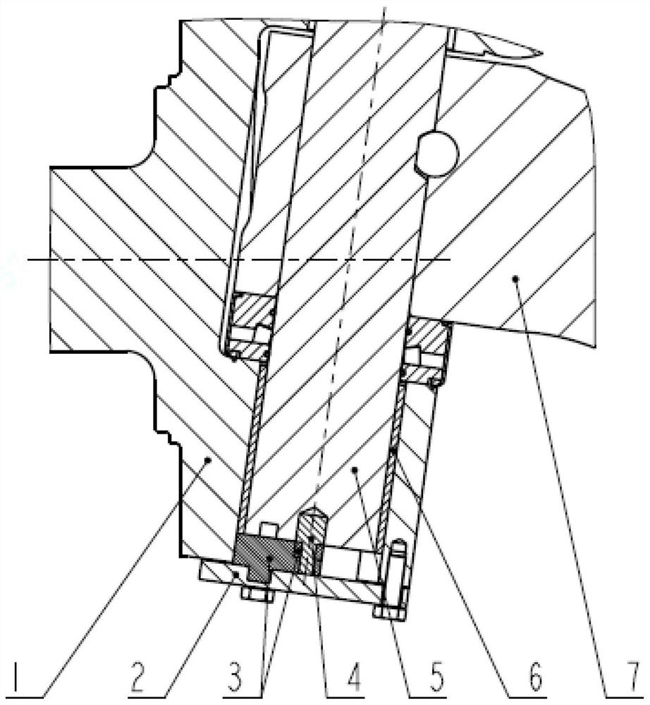
[0018] figure 1 Shown is the structural representation of the present invention.

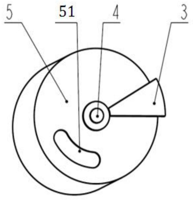
[0019] figure 2 Shown is the structural representation of kingpin assembly of the present invention.

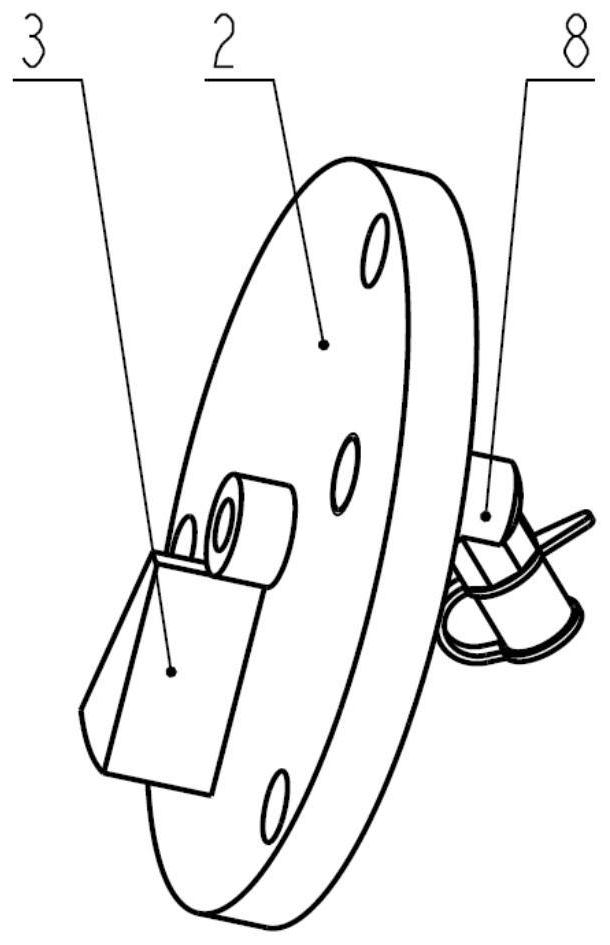
[0020] image 3 Shown is a schematic structural view of the kingpin cover assembly of the present invention.

[0021] The present invention provides a dynamic lubricating structure for kingpin bushing, which includes front beam 7, steering knuckle 1, bushing 6, kingpin assembly and kingpin cover assembly. There is a lubricating grease passage on the bushing 6. press into the kingpin hole of the steering knuckle in the way of interference; the kingpin assembly includes the kingpin 5, the partition block 3 and the partition block pin shaft 4, the oil groove 51 is processed on the end surface of the kingpin 5, and the kingpin assembly Penetrate the kingpin hole o...


PUM


Abstract

The invention discloses a kingpin bushing dynamic lubrication structure. The kingpin bushing dynamic lubrication structure comprises a front beam, a steering knuckle, bushing, a kingpin assembly and akingpin cover assembly, a lubricating grease oil duct bush is arranged on the bushing, and the bushing is pressed into a kingpin hole of the steering knuckle in an interference mode. The kingpin assembly comprises a kingpin, a separation block and a separation block pin shaft, an oil passing groove is machined in the end face of the kingpin, and the kingpin assembly penetrates into kingpin hole in the steering knuckle and the front beam to connect the steering knuckle with the front beam and enable the steering knuckle to rotate around the front beam. The kingpin cover assembly comprises a kingpin cover, a separation block and a grease nozzle, and is screwed and fixed to the steering knuckle through a bolt. Grease is injected into a lubricating grease storage cavity from the grease nozzle, and the friction faces of the kingpin and the bushing are fully filled with the grease under the pressure effect of a grease injection gun. According to the kingpin bushing dynamic lubrication structure, under the action of the structure, the friction surfaces of the kingpin and the bushing are always kept fully lubricated, dry grinding of the kingpin and the bushing is avoided, and the servicelife of the bushing is prolonged.

Description

technical field [0001] The invention relates to a steering knuckle bush lubricating structure for a commercial vehicle, and relates to the field of auto parts. Background technique [0002] Steering mechanism, as an important component of vehicle safety, must have sufficient reliability. A steering knuckle is installed at both ends of the front axle assembly, and is connected to both ends of the I-beam through the kingpin. When the vehicle turns, under the actuation of the output force of the steering machine, the steering knuckle can rotate around the kingpin to realize the steering of the vehicle. In order to avoid the direct wear of the steering knuckle and the kingpin, bushings are installed in the upper and lower kingpin holes of the steering knuckle and lubricated. However, due to the heavy weight of commercial vehicles, the bushings are subject to great pressure and will inevitably be worn , especially when the lubricating conditions are not good, the bushing will we...

Claims


Application Information

Patent Timeline
IPC IPC(8): F16C33/10F16N1/00B62D7/18
CPCF16C33/102F16N1/00B62D7/18F16C2326/24
Inventor 曹振虎孔卓薄瑶马兵兵刘宏威
Owner SINO TRUK JINAN POWER
Why Eureka
Try Eureka