
Multi-angle adjusting bracket for computer display

A technology for adjusting brackets and monitors. It is applied in the directions of machines/brackets, instruments, and supporting machines. It can solve the problems of poor structural stability, easy to loose, and difficult to adjust, and achieve the effect of easy support, compact and stable structure, and easy installation.

Inactive Publication Date: 2020-12-04
蔡益民
View PDF9 Cites 0 Cited by
  • Summary
  • Abstract
  • Description
  • Claims
  • Application Information

AI Technical Summary

Problems solved by technology

[0003] The adjustment bracket of the prior art computer monitor has a simple structure, and is generally locked and fixed in the preset installation hole by bolts, which makes the installation efficiency relatively poor, and the angle adjustment is mostly performed manually, which is not easy to carry out when it is installed at a high place. Adjustment, and it is easy to loosen when used for a long time, and the structural stability is relatively poor

Method used


Image

  • Multi-angle adjusting bracket for computer display
  • Multi-angle adjusting bracket for computer display
  • Multi-angle adjusting bracket for computer display

Examples


Embodiment 1

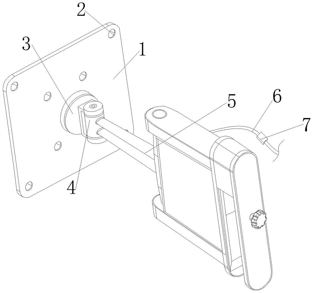
[0030] see figure 1 , a multi-angle adjustment bracket for a computer monitor of the present invention, comprising a mounting piece 1, a fixing hole 2, a cushion block 3, a connecting block 4, an adjustment assembly 5, a power cord 6 and a control switch 7, and the four ends of the mounting piece 1 are provided with There is a fixing hole 2, the rear side of the adjustment component 5 is fixed with the connection block 4, the front side of the installation piece 1 is integrally formed with a spacer 3, the middle side of the front part of the spacer 3 is fixed with the connection block 4, and the power cord 6 is set on On the right side of the adjustment assembly 5, a control switch 7 is arranged inside the power cord 6.

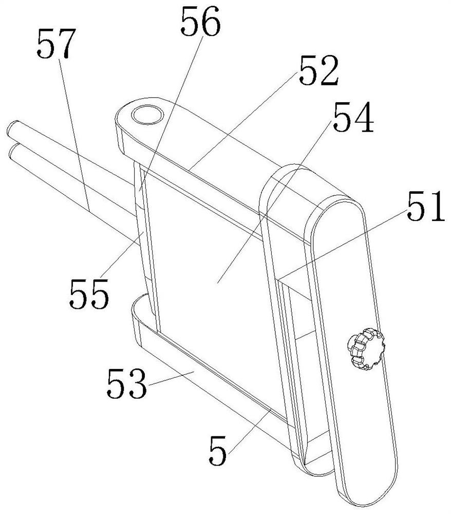
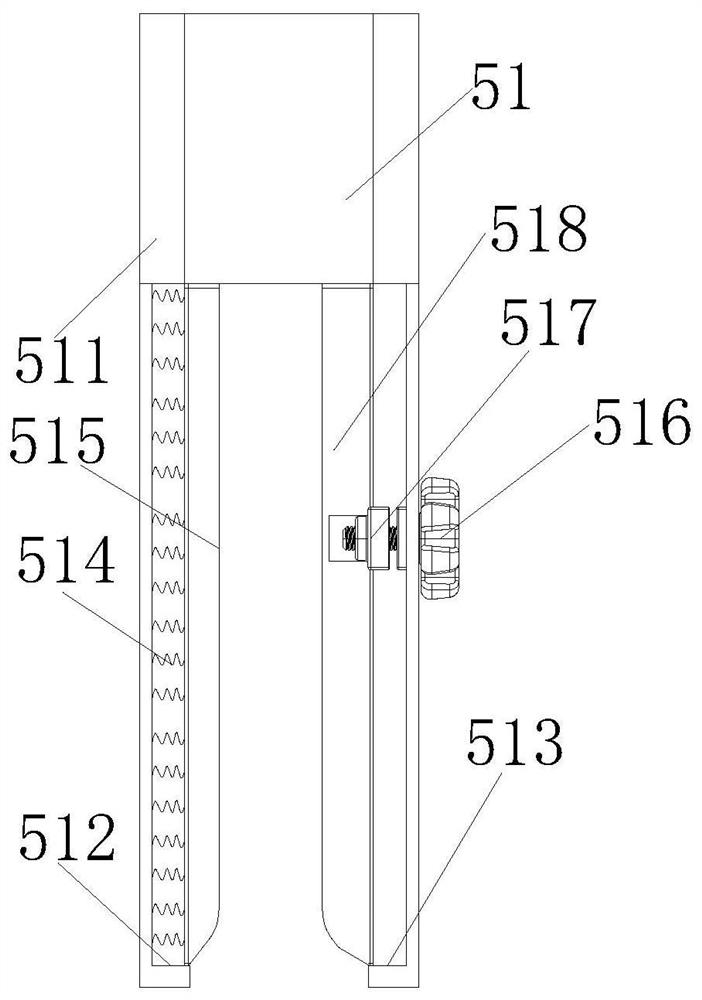
[0031] see figure 2 and Figure 4 , a multi-angle adjustment bracket for a computer monitor of the present invention, the adjustment assembly 5 includes a fixed structure 51, a rotating structure 52, a base plate 53, a telescopic steering structure 54, a s...

Embodiment 2

[0036] In the multi-angle adjustment bracket for a computer monitor of the present invention, the left splint 515 and the right splint 518 are symmetrically arranged in the middle of the inner side of the frame cover 511, and the inner bottoms of the left splint 515 and the right splint 518 are all provided with rounded corners, which is convenient for installation , the number of springs 514 is not less than ten, and the springs 514 are equidistantly distributed on the left side of the left splint 515, which is convenient for supporting the left support plate 515. The rectangular seat 521 has the same structure size as the bottom plate 53, and the rectangular seat 521 and The inside of the bottom plate 53 is hollow to reduce the overall weight. The size ratio of the driving bevel gear 523 and the driven bevel gear 524 is 1:2, and the angle formed between the driving bevel gear 523 and the driven bevel gear 524 is 90 degrees. , to facilitate the steering transmission of deceler...


PUM


Abstract

The invention discloses a multi-angle adjusting bracket for a computer display, which comprises a mounting piece, fixing holes, a cushion block, a connecting block, an adjusting assembly, a power lineand a control switch. According to the multi-angle adjusting bracket, the adjusting assembly is optimally arranged, and a right clamping plate can get close to a left clamping plate by rotating a small-threaded rotating rod so that a position required to be mounted can be rapidly clamped; a driving motor, a first servo motor and a second servo motor are used as power sources, electric power is used for driving, a supporting rod frame and a frame cover are enabled to rotate under the effect of the driving motor, and a sliding block can transversely move and rotate at the inner side of the supporting rod frame through starting of the first servo motor and the second servo motor to realize multi-angle adjustment of a connecting rod; besides, the structure is compact and stable, and the overall stability and practicability are improved.

Description

technical field [0001] The invention relates to the related field of monitor brackets, in particular to a multi-angle adjustable bracket for computer monitors. Background technique [0002] Computer monitor stand is a product that can fix computer monitors, which can help solve various technical problems that people encounter when operating computers at home or in commercial offices. Its ergonomic design can prevent health problems caused by work fatigue , improve work efficiency, and increase the ideal space for living and working. [0003] The adjustment bracket of the prior art computer monitor has a simple structure, and is generally locked and fixed in the preset installation hole by bolts, which makes the installation efficiency relatively poor, and the angle adjustment is mostly performed manually, which is not easy to carry out when it is installed at a high place. Adjustment, and it is easy to loosen when used for a long time, and the structural stability is relati...

Claims


Application Information

Patent Timeline
IPC IPC(8): F16M11/04F16M11/12F16M11/18F16M13/02G06F1/16
CPCF16M11/04F16M11/12F16M11/18F16M13/02G06F1/1601
Inventor 蔡益民
Owner 蔡益民
Learn More