Detection equipment for detecting performance of stove

A technology for testing equipment and cooking utensils, which is applied in the field of cooking utensils, can solve problems such as inaccurate travel of temperature sensors, affect inspection efficiency, and hidden dangers of hand burns, and achieve the effects of improving safety in use, reducing manufacturing costs, and eliminating hidden dangers of hand burns

Pending Publication Date: 2020-12-04
VATTI CORP LTD
View PDF0 Cites 0 Cited by
  • Summary
  • Abstract
  • Description
  • Claims
  • Application Information

AI Technical Summary

Problems solved by technology

This inspection method requires an additional inspection of whether the temperature sensor or the pulse igniter is faulty when the cooker does not cut off the gas source and turn off the fire. Due to the high resistance value and corresponding temperature of the temperature sensor design, the combustion inspection takes a long time. Affects the inspection efficiency, and if the pan is placed above the temperature sensor with bare hands and the temperature sensor is pressed down, there will be a hidden danger of burning hands and a risk of inaccurate travel of the pressed temperature sensor

Method used


Image

  • Detection equipment for detecting performance of stove
  • Detection equipment for detecting performance of stove
  • Detection equipment for detecting performance of stove

Examples


Embodiment 1

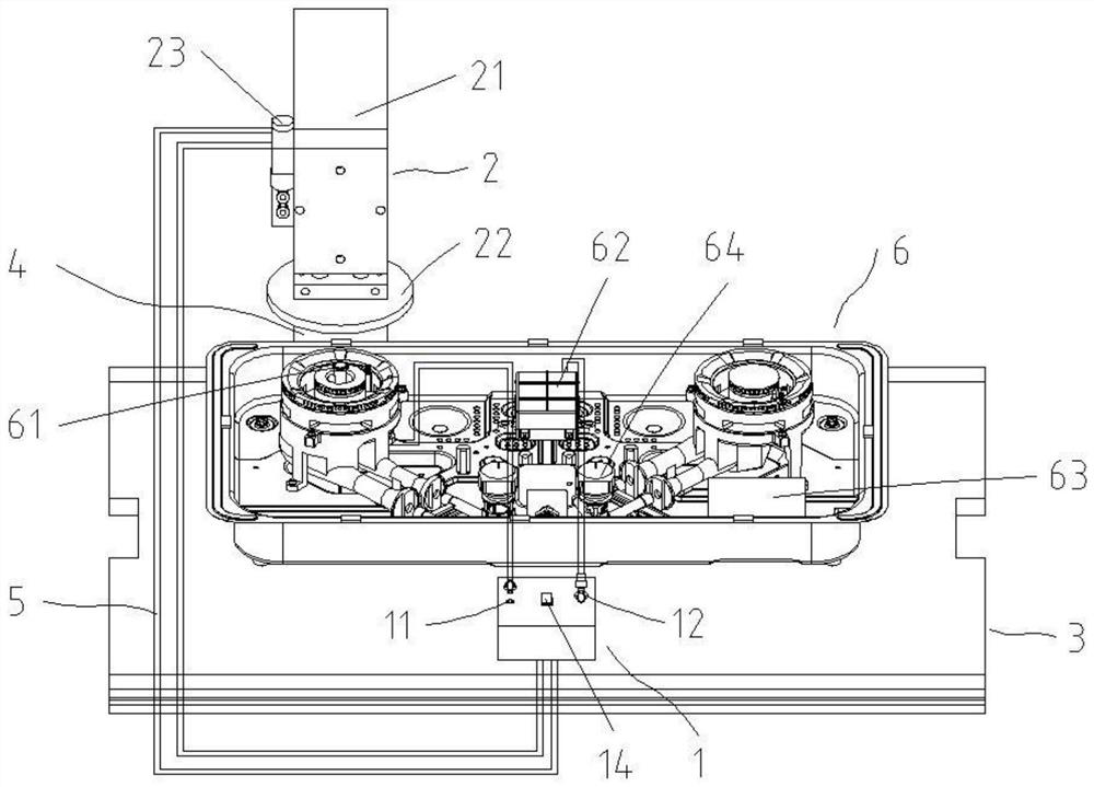
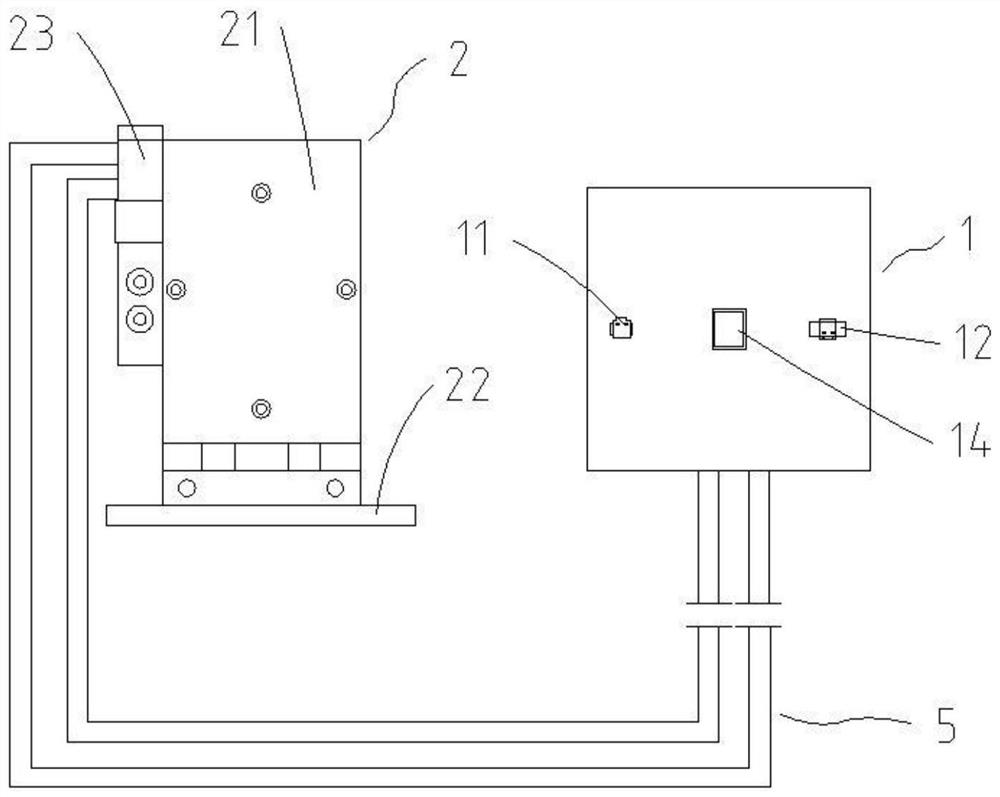
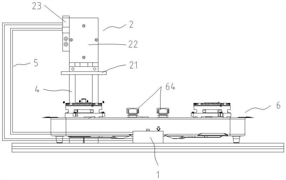
[0028] see Figure 1-6 , this embodiment provides a detection device for detecting the performance of a cooker, including a rheostat box assembly 1 and a pot simulation assembly 2 for pressing the temperature sensor of the cooker, wherein the rheostat box assembly 1 is provided with a temperature sensor terminal 11, The pulse igniter connection terminal 12 and switch 14, the temperature sensor connection terminal 11 is used to electrically connect the temperature sensor 61 of the cooker 6 through the wire 5, the pulse igniter connection terminal 12 is used for the pulse igniter of the cooker 6 through the wire 5 62 is electrically connected, and the pulse igniter 62 and the temperature sensor 61 are respectively connected to the power supply 63 of the cooker 6 . One end of the switch 14 is connected to the terminal 12 of the pulse igniter, and the other end is selectively connected to the pot simulation component 2 through the electric wire 5 . see Figure 6 , when the switc...

Embodiment 2

[0045] refer to Figure 7 , the difference between this embodiment and Embodiment 1 is that the temperature sensor simulator 13 is omitted, and the switch 14 is selectively connected to the electric converter 23, that is, the switch 14 has no rated resistance gear, but it has at least one There is no rated resistance file, and other parts are the same as in Embodiment 1.

[0046] It can be seen that by omitting the temperature sensor simulator 13, the structure and circuit diagram of the entire detection device are simplified, which is beneficial to reduce the manufacturing cost of the detection device.

Embodiment 3

[0048] The difference between this embodiment and Embodiment 1 is that the temperature sensor simulator 13, production line, detection module and assembly line board 3 are omitted, the rheostat box assembly 1 is installed on the preset installation station, and the pot simulation assembly 2 passes The installation bracket 4 is installed on the preset installation station, and the end of the switch 14 away from the pulse igniter terminal 12 is selectively connected to the electric converter 23, and other parts are the same as in the first embodiment.

[0049] It can be seen that by omitting the temperature sensor simulator 13, the production line, the detection module and the assembly line board 3, the structure and circuit diagram of the entire detection equipment are simplified, making the detection equipment suitable for laboratory use, and more convenient to move the detection equipment.


PUM


Abstract

The invention discloses detection equipment for detecting the performance of a stove. The detection equipment comprises a variable resistance box assembly and a cookware simulation assembly which is used for pressing a temperature sensor of a stove, wherein the variable resistance box assembly is provided with temperature sensor wiring terminals, pulse igniter wiring terminals and a change-over switch, one end of the change-over switch is connected with the pulse igniter wiring terminals, and the other end is selectively connected with the cookware simulation assembly. According to the detection equipment, the change-over switch is controlled to be connected with the cookware simulation assembly, so that the performance of the temperature sensor of the stove can be accurately detected, andwhether the temperature sensor breaks down or not can be distinguished; and the cookware simulation assembly is adopted to press the temperature sensor of the stove, the hidden danger that hands areburnt when a user holds a cookware with hands can be eliminated, and the use safety of detection equipment is improved.

Description

technical field [0001] The invention relates to the technical field of cooking utensils, in particular to a technology for detecting the performance of cooking utensils. Background technique [0002] At present, cooker products have the function of preventing dry burning. When the temperature sensor is heated by fire or the radiation temperature of the pot increases, the resistance value will continue to increase with the temperature. When the resistance value reaches the specified value, after a period of time, the temperature sensor will feedback signal To the pulse igniter, the pulse igniter sends a signal to the solenoid valve, thereby cutting off the gas source and turning off the fire. It can be seen that the temperature sensor and the pulse igniter play a very important role in the anti-dry function. Therefore, the performance of the two components needs to be tested. [0003] When the production line detects the performance of the temperature sensor and the pulse ig...

Claims


Application Information

Patent Timeline
Patent Type & Authority Applications(China)
IPC IPC(8): G01R31/01G01K15/00
CPCG01K15/007G01R31/01
Inventor 麦均叨曹开银李宗洋汪泉麦志峰潘叶江
Owner VATTI CORP LTD
Why Eureka
Try Eureka