
Control method for automatic testing IC complete device

A technology for integrated circuit and complete machine testing, applied in electronic circuit testing, semiconductor/solid-state device testing/measurement, etc., can solve problems such as software conflicts, dynamic errors that cannot be detected, errors, etc., to improve accuracy and complete testing. , excellent quality effect

Inactive Publication Date: 2007-11-28
VIA TECH INC
View PDF2 Cites 0 Cited by
  • Summary
  • Abstract
  • Description
  • Claims
  • Application Information

AI Technical Summary

Problems solved by technology

[0008] 1. The known integrated circuit test cannot simulate the final use state of the user, so even if it passes the test, problems may occur when the user uses it, such as conflicts with software, etc.
[0009] 2. It is known that all the components placed on the test circuit board are the same type during the test of the known integrated circuit, and the compatibility problem between different components cannot be detected.
[0010] 3. The known test methods still rely on a lot of labor, which limits the production capacity and cost, and also causes the possibility of human error
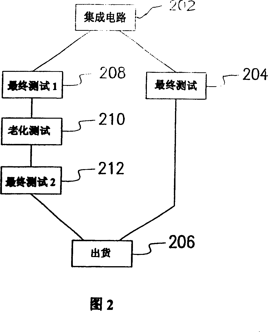
[0011] 4. The known test method for integrated circuit modules cannot control the operating temperature of the components after the integrated circuit is assembled, that is, at the module stage, so it cannot be simulated for certain states in actual use.
[0012] 5. The judgment of known tests is generally based on the final integrated circuit state, and some dynamic errors cannot be detected. For example, in the case of graphics accelerators, image drift (video shaking) and hue variation generated during actual program execution Phenomena such as discoloring display, ghost shallow or white block cannot be detected
Or crashes caused by integrated circuit software execution, etc., cannot be detected by traditional testing methods

Method used


Image

  • Control method for automatic testing IC complete device
  • Control method for automatic testing IC complete device
  • Control method for automatic testing IC complete device

Examples


Embodiment Construction

[0089] The automatic integrated circuit test equipment, device and method of the present invention are performed on a known good computer, and can be used to detect any integrated circuit in the test computer. In terms of personal computers, such as central processing units, system bus controllers, input / output bus controllers, or integrated circuits in interface modules, such as graphics accelerators. Generally speaking, these integrated circuits are configured on a printed circuit board, such as a central processing unit, a system bus controller, and an input / output bus controller are usually configured on a motherboard. Among them, the central processing unit is usually electrically connected to the motherboard through a connector, such as Socket 478, Socket 423, Socket 370, Socket 7, etc. The memory integrated circuit is configured on a module circuit board, and then is electrically connected to the motherboard through a connector, such as DIMM, RIMM, etc. As for the system bu...


PUM


Abstract

The test flow includes the following steps. The drive-automatic transporter picks up the IC to be tested on the provision device, sending it to each testing computer. The drive-automatic plugging and pulling out mechanism connects the IC to be tested with the corresponding testing computer. The preset testing program in the testing computer is started to run, meanwhile, the image monitor is started to enter in the monitoring and executing state in order to determine whether each ICin normal or not. Then, the drive-automatic plugging and pulling out mechanism takes the IC tested off from the testing computer. The drive-automatic transporter sends the IC to the IC sorted, which sorts ICs based on the tested result.

Description

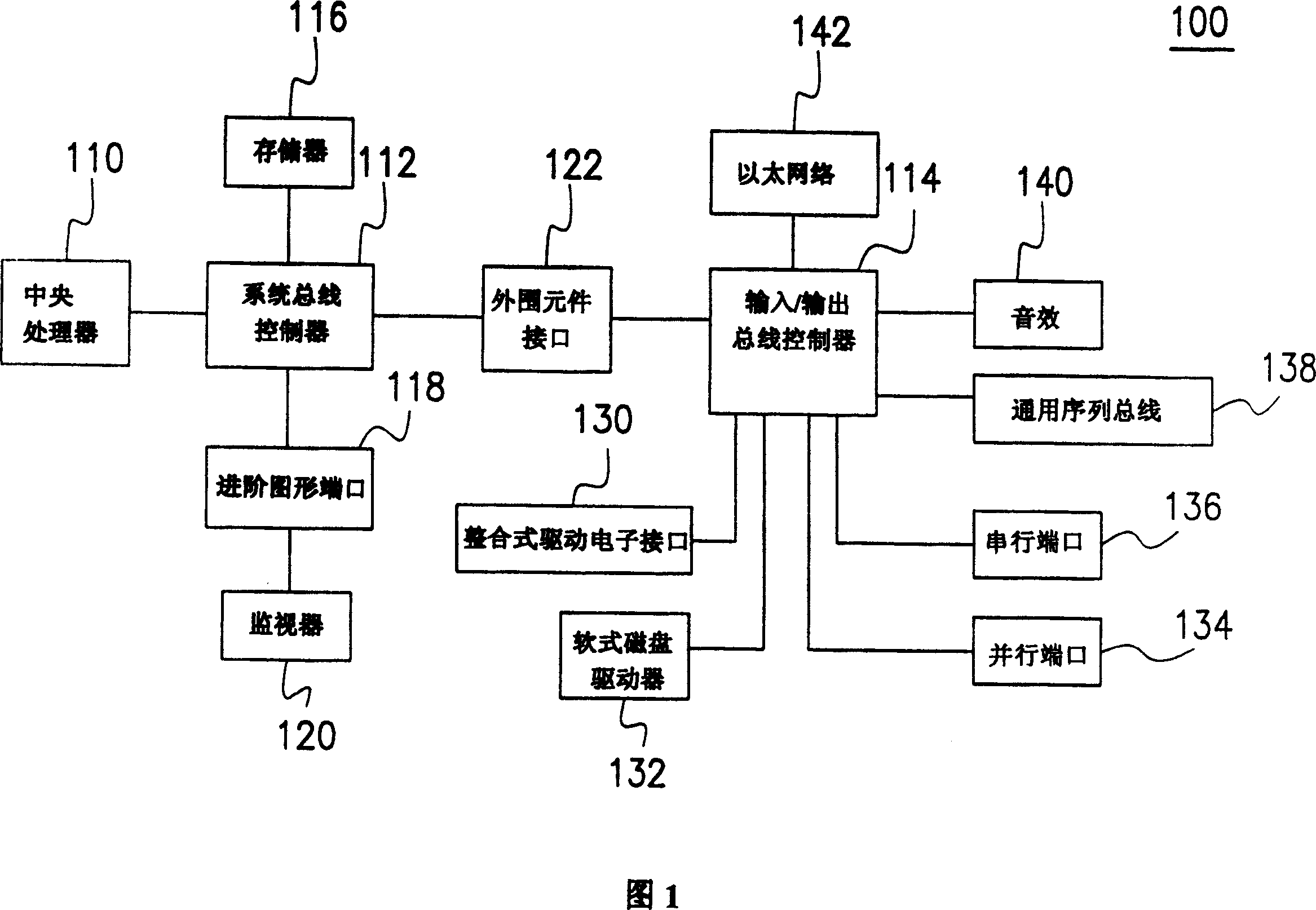
Technical field [0001] The present invention relates to an automated integrated circuit complete machine testing equipment, device and method, and in particular to an automated integrated circuit complete machine testing equipment, device and method that can simulate the state of the end user and perform dynamic testing method. Background technique [0002] Computers have almost become one of the necessities of life for today’s humans, no matter the server (server), workstation (Workstation), desktop computer (notebook computer) or portable computer (portable computer), Or personal digital assistants, palm-top PCs, pocket PCs, or even industrial computers, which have become part of most people's daily lives. These computers are composed of many integrated circuits (ICs), and these integrated circuits must undergo complicated tests to ensure the quality of the products. [0003] Please refer to FIG. 1, which is a diagram of a well-known personal computer (PC) architecture. The wel...

Claims


Application Information

Patent Timeline
Patent Type & Authority Patents(China)
IPC IPC(8): H01L21/66G01R31/28
Inventor 祁明仁郭澎嘉
Owner VIA TECH INC
Learn More