Beam scanning method based on frequency domain Bark sub-band, and sound source orientation device

A technology of beam scanning and frequency domain, applied in direction finders using ultrasonic/sonic/infrasonic waves, systems for determining direction or offset, etc., can solve problems such as being easily affected by noise bands, algorithm failure, and high computational complexity. Achieve the effect of improving the sound source orientation accuracy and reducing the computational complexity

Pending Publication Date: 2020-12-04
北京中电慧声科技有限公司 +1
View PDF0 Cites 4 Cited by
  • Summary
  • Abstract
  • Description
  • Claims
  • Application Information

AI Technical Summary

Problems solved by technology

The shortcomings of the traditional sub-band beam scanning method are that it does not make full use of the frequency characteristics of the voice signal, and uses full-band orientation, which

Method used


Image

  • Beam scanning method based on frequency domain Bark sub-band, and sound source orientation device
  • Beam scanning method based on frequency domain Bark sub-band, and sound source orientation device
  • Beam scanning method based on frequency domain Bark sub-band, and sound source orientation device

Examples


Embodiment 1

[0056] Beam Scanning Method Based on Bark Subband in Frequency Domain

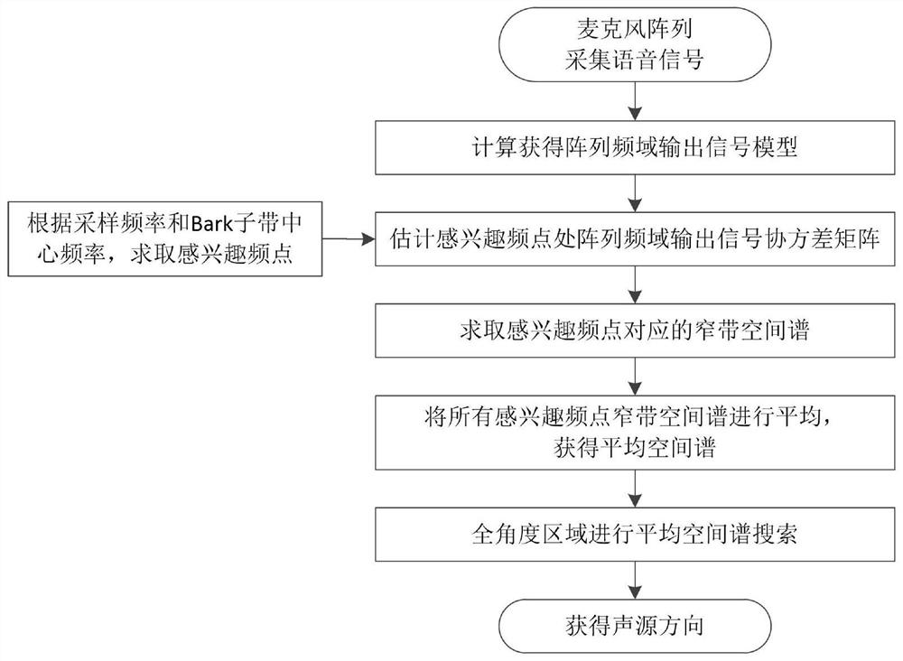
[0057] Such as figure 1 Shown, a kind of beam scanning method based on frequency domain Bark subband comprises the following steps:

[0058] Step 1: The microphone array collects sound signals, and calculates and obtains the array frequency domain output signal model.

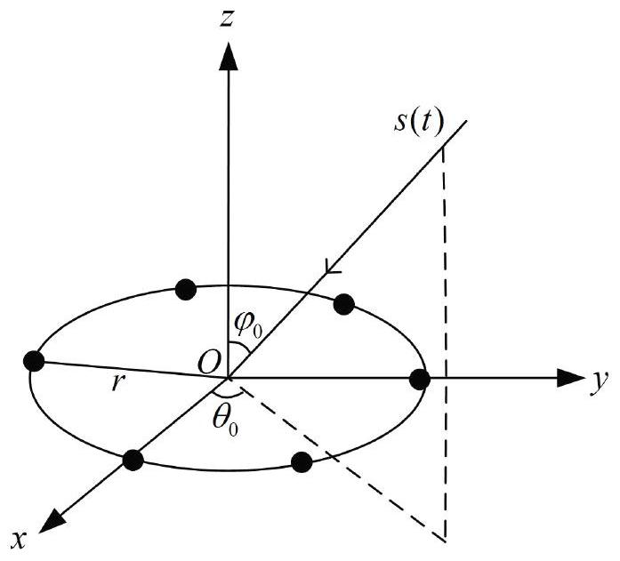
[0059] Such as figure 2 As shown, the uniform circular array is taken as an example to establish a mathematical model for broadband signal processing. Assume that the broadband signal (sound signal) s(t) is incident from the far field on a circular array uniformly distributed by N isotropic microphones, the radius of the circular array is r, and the center of the array (the center of the circle) is the reference origin; set the incident signal The pitch angle is The azimuth is θ 0 ∈[0°,360°]; the noise of each microphone array element is spatial white noise, that is, each noise is independent of each other; noise and signal are indep...

Embodiment 2

[0100] Sound source directional device based on microphone array

[0101] Such as Figure 7 As shown, a sound source directional device based on a microphone array includes:

[0102] Microphone array, described microphone array is used for collecting sound signal;

[0103] The average spatial spectrum calculation unit, the average spatial spectrum calculation unit is used to perform the following operations: calculate and obtain the array frequency domain output signal model; obtain the frequency point of interest according to the sampling frequency and the center frequency of the Bark sub-band; estimate the frequency point of interest The covariance matrix of the output signal in the frequency domain of the array; calculate the narrowband spatial spectrum corresponding to the frequency point of interest; average the narrowband spatial spectrum of all frequency points of interest to obtain the average spatial spectrum;

[0104] A sound source directional unit, the sound sour...


PUM


Abstract

The invention relates to a beam scanning method based on a frequency domain Bark sub-band, and a sound source orientation device. The method comprises the following steps: 1, collecting a sound signalthrough a microphone array, and obtaining an array frequency domain output signal model through calculation; 2, solving interested frequency points according to the sampling frequency and the centerfrequency of the Bark sub-band, and estimating a covariance matrix of array frequency domain output signals at the interested frequency points; 3, calculating a narrow-band spatial spectrum corresponding to the interested frequency points; 4, averaging the narrow-band spatial spectra of all interested frequency points to obtain an average spatial spectrum; and 5, carrying out average spatial spectrum search in the full-angle area to obtain a sound source direction. The sound source orientation precision is effectively improved, and the operation complexity is reduced.

Description

technical field [0001] The invention relates to a frequency-domain Bark sub-band-based beam scanning method and a sound source directional device. Background technique [0002] Sound source orientation based on microphone array is an important problem in speech signal processing, and it has a wide range of applications in video conferencing, intelligent monitoring, human-computer voice interaction and other fields. The sound source orientation methods based on the microphone array can be roughly divided into three categories: the orientation method based on the time difference of arrival, the steerable beamforming method based on the maximum output power, and the orientation method based on high-resolution spectrum estimation. [0003] Since speech signals belong to broadband signals, traditional sound source directional methods based on high-resolution spectrum estimation mostly use the sub-band beam scanning method when processing broadband signals. According to the method...

Claims


Application Information

Patent Timeline
IPC IPC(8): G01S3/802
CPCG01S3/802
Inventor 王荔张小博陈龙
Owner 北京中电慧声科技有限公司
Why Eureka
Try Eureka