Check patentability & draft patents in minutes with Patsnap Eureka AI!

Photovoltaic energy remote monitoring system

A remote monitoring system and energy technology, applied in the monitoring of photovoltaic systems, photovoltaic power generation, photovoltaic modules, etc., can solve the problems of dust attachment, large display area, inconvenient cleaning methods, etc., to avoid shaking and misoperation , the effect of good practical value

Inactive Publication Date: 2020-12-04
HXXN ELECTRICITY
View PDF7 Cites 0 Cited by
  • Summary
  • Abstract
  • Description
  • Claims
  • Application Information

AI Technical Summary

Problems solved by technology

[0003] Most of the photovoltaic equipment currently on the market needs to be monitored remotely to observe whether the equipment is operating normally. It also has a monitoring function to prevent criminals from stealing. Generally, there are multiple photovoltaic equipment, which requires multiple display screens for observation. , the display screen of the existing monitoring equipment is generally set in multiple groups. When it is used for a long time, a large amount of dust will inevitably adhere to the surface. The general cleaning method needs to clean the surface with a wet rag. This method One is that there will be water droplets on the surface of the display screen. Once the water droplets enter the device through the gap, it may affect the normal use of the device, and the traditional cleaning method is very inconvenient because of the large area occupied by multiple display screens. Therefore, for the above The problem proposes a photovoltaic energy remote monitoring system

Method used


Image

  • Photovoltaic energy remote monitoring system
  • Photovoltaic energy remote monitoring system
  • Photovoltaic energy remote monitoring system

Examples


Embodiment 1

[0026] see figure 1 , figure 2 , image 3 , Figure 4 , Figure 5 , Figure 6 and Figure 7 , the present invention provides a technical solution:

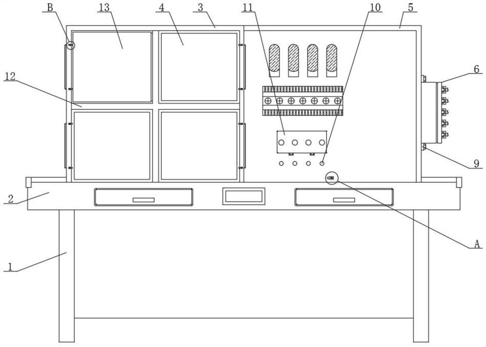
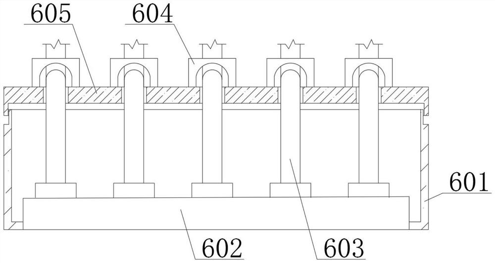
[0027]A photovoltaic energy remote monitoring system, comprising a support leg 1 and a platform 2, the upper end surface of the support leg 1 is fixedly connected with the platform 2, and the left side of the upper end surface of the platform 2 is fixedly connected with a fixed frame 3, and the fixed frame 3 functions as a fixed display screen 4 Purpose, the right side of the upper end surface of the platform 2 is fixedly connected with the control panel 5, the right side of the right end surface of the control panel 5 is provided with a screw 9, the screw 9 can fix the connecting device 6, and the outer side of the screw 9 is spirally connected with the control panel 5 and the connecting Device 6, the connection device 6 includes a connection frame 601 and a connection plate 602, the left end surface of the connection fram...

Embodiment 2

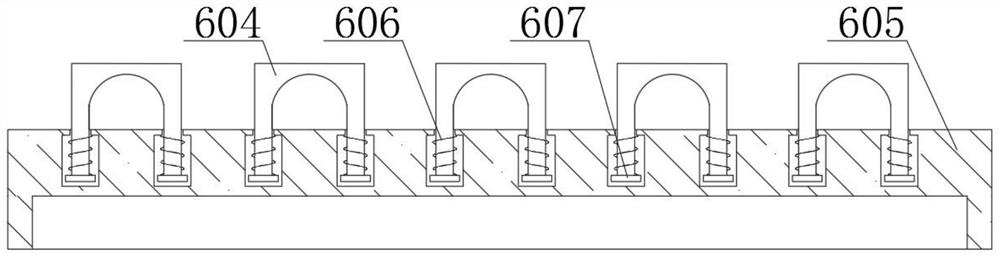
[0030] In embodiment 2, the same parts as in embodiment 1 will not be repeated. The difference is that when a large amount of dust is stained on the surface of the protective plate 13, the sliding frame 804 is moved to both sides to make it drive the sliding rod 801 to compress the telescopic spring 803, then the sliding rod 801 is separated from the protective plate 13, and now the protective plate 13 can be separated from the limit frame 12, so that it can be taken out, and then it can be cleaned. Centralized treatment, water will not directly contact with the display screen 4, ensuring normal use of the equipment and saving time.


PUM


Abstract

The invention relates to the technical field of photovoltaic energy remote monitoring, particularly to a photovoltaic energy remote monitoring system, which comprises supporting legs and a platform, wherein the upper end faces of the supporting legs are fixedly connected with the platform, the left side of the upper end face of the platform is fixedly connected with a fixing frame, the right sideof the upper end face of the platform is fixedly connected with a control panel, a screw is arranged on the right side of the right end face of the control panel, the outer side of the screw is in threaded connection with the control panel and a connecting device which are distributed left and right, operation buttons which are evenly distributed are fixedly connected to the front side of the control panel, and a rotating cover is arranged above the operation buttons. According to the invention, through mutual cooperation of a protection plate and a limiting frame, a display screen can be protected, and when dust exists on the surface of the display screen, only the protection plate needs to be cleaned by taking out the protection plate, so that the generated water drops cannot drop into equipment at the moment, and normal use of the equipment is guaranteed.

Description

technical field [0001] The invention relates to the technical field of photovoltaic energy remote monitoring, in particular to a photovoltaic energy remote monitoring system. Background technique [0002] Photovoltaic energy systems generally include solar cells or components, charge and discharge control systems (or inverters) and load control. Solar cells are devices that convert solar radiation energy into electrical energy based on the photovoltaic effect. Affected by load and other factors, it is difficult for solar cells to obtain stable DC output. Therefore, most solar systems currently need to store energy through batteries before supplying power to the outside. The main function of the charge and discharge controller is to control the charge and discharge process of the batteries in the system. , To prevent the battery from being damaged due to overcharging or over-discharging, the function of the inverter is to convert the low-voltage direct current output by the b...

Claims


Application Information

Patent Timeline
IPC IPC(8): H02S50/00H02S40/30H02J13/00H05K5/00H05K5/02H05K5/03H02G3/02H01H9/02G09F9/30
CPCH02S50/00H02S40/30H02J13/00001H02J13/00002H02J13/00032H05K5/0017H05K5/0217H05K5/0247H05K5/03H02G3/02H01H9/02G09F9/30Y02E10/50Y04S10/40
Inventor 周斌曹应平李文芳黎灿兵游玫瑰张聪
Owner HXXN ELECTRICITY
Features
  • R&D
  • Intellectual Property
  • Life Sciences
  • Materials
  • Tech Scout
  • Unparalleled Data Quality
  • Higher Quality Content
  • 60% Fewer Hallucinations
Learn More