Floating-caliper brake

A floating caliper and brake technology, applied in the direction of brake type, axial brake, brake components, etc., can solve problems such as consumption

Inactive Publication Date: 2020-12-04
VE VIENNA ENG FORSCHUNGS & ENTWICKLUNGS
View PDF19 Cites 1 Cited by
  • Summary
  • Abstract
  • Description
  • Claims
  • Application Information

AI Technical Summary

Problems solved by technology

Although the brake lining can be reliably lifted in this way, this realization can be practically expensive, especially to prot

Method used


Image

  • Floating-caliper brake
  • Floating-caliper brake
  • Floating-caliper brake

Examples


Embodiment Construction

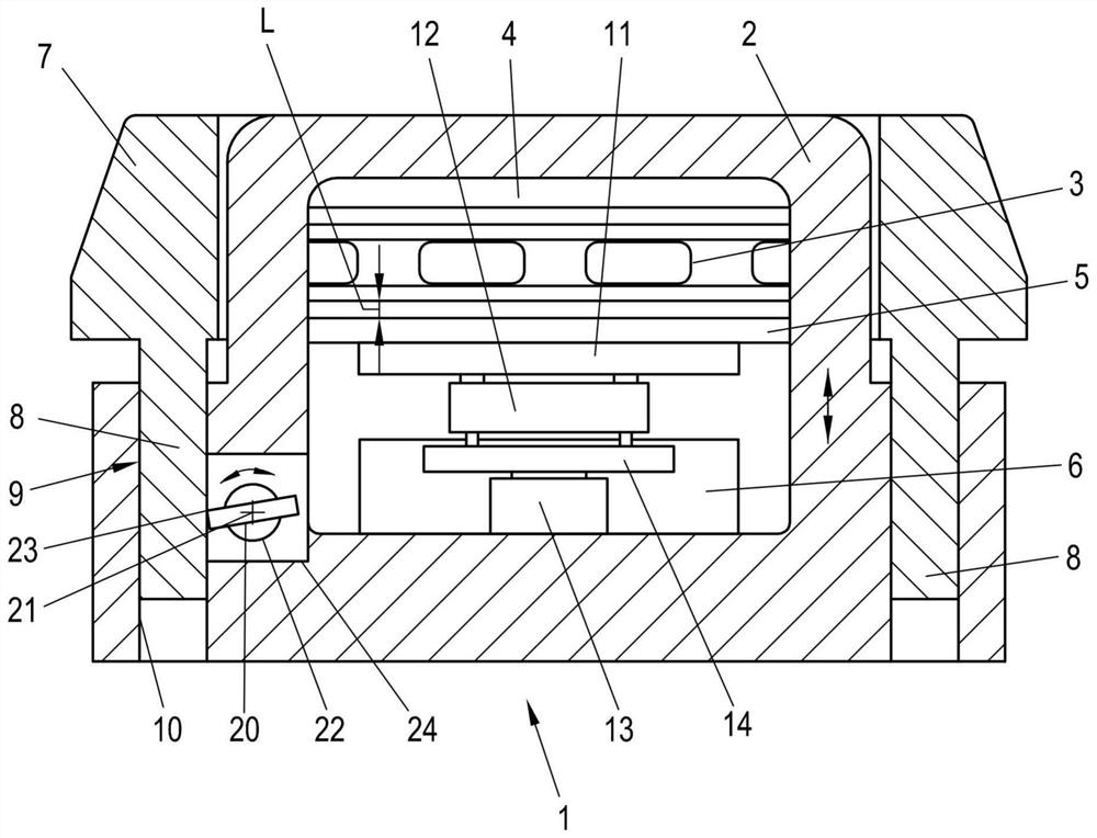
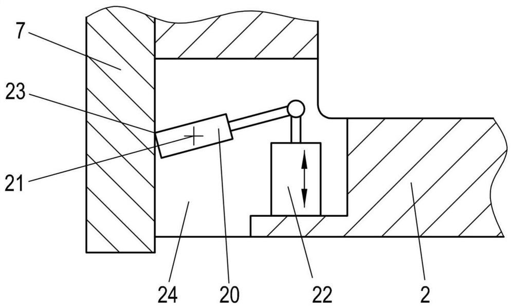
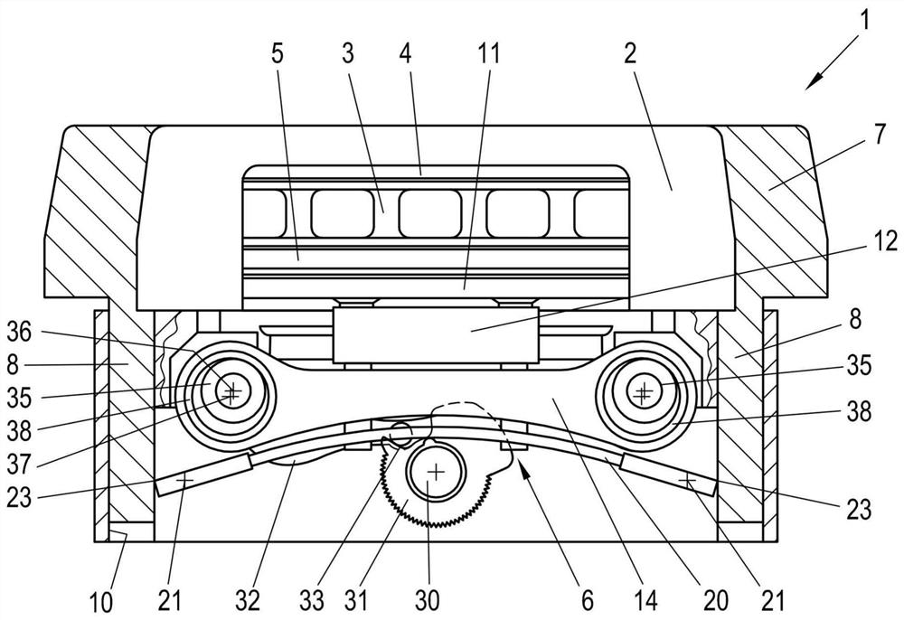
[0018] The floating caliper brake 1 essentially comprises a floating-mounted brake caliper 2 and a hold-down device 6 , on which the brake caliper is generally rigid (ie immovable relative to the brake caliper 2 but of course replaceable depending on requirements) A first brake lining 4 is provided on which, of course, a second brake lining 5 is arranged (replaceable depending on requirements, of course). For braking, the two brake linings 4 , 5 cooperate with the brake disk 3 . The second brake lining 5 can be moved relative to the brake caliper 2 by means of the pressing device 6 , in particular the second brake lining 5 can be moved towards the first brake lining 4 or away from said first brake lining. Pieces of movement. The floating caliper brake 1 serves to brake translational movements (eg in the case of lifting brakes or linearly moving mechanical parts) or rotational movements (eg of a vehicle wheel or a rotating mechanical part). For this purpose, the two brake lin...


PUM


Abstract

The aim of the invention is to ensure a reliable lift of both brake pads of a floating-caliper brake (1) after releasing the brake. This is achieved in that a lifting part (20) is hinged to the brakecaliper (2) at a hinge point (21), and the lifting part (20) is supported on the support structure (7) at a contact point (23) at least partly upon releasing the floating-caliper brake (1), wherein alift drive (22) is provided which rotates the lifting part (20) about the hinge point (21) such that a support for the lifting part (20) is produced on the contact point (23), whereby the hinge point(21) and the brake caliper (2) are moved.

Description

technical field [0001] The invention relates to a floating caliper brake having a brake caliper floatingly supported on a support structure of the floating caliper brake, on which brake caliper a first brake lining is arranged plate and hold-down device, wherein a second brake lining is provided on the hold-down device and the hold-down device orients the second brake pad towards the A first brake lining is moved and a second brake lining is moved away from the first brake lining in order to release the floating caliper brake. Background technique [0002] Caliper disc brakes, in particular as disc brakes, are used very widely and in particular in vehicles and machines. In the known embodiment of a floating caliper brake as a caliper disc brake, at least one brake lining is advanced against the brake disc by means of a pressing device during braking in a known manner. As soon as said brake lining is in contact with the brake disc, the opposite second brake lining is advanc...

Claims


Application Information

Patent Timeline
IPC IPC(8): F16D55/22F16D65/09F16D65/14F16D65/18
CPCF16D55/2265F16D65/18F16D2055/0029F16D55/226F16D65/0043F16D65/092F16D65/183F16D2250/0084F16D65/005F16D55/227F16D65/0056F16D65/0068F16D65/0087F16D2055/0008
Inventor M·普茨
Owner VE VIENNA ENG FORSCHUNGS & ENTWICKLUNGS
Why Eureka
Try Eureka