Spraying equipment for aeronautical parts

A technology of spraying equipment and aviation parts, applied in the aerospace field, can solve the problems of pigment waste, reduce work intensity, increase production cost, etc., and achieve the effects of reducing production cost, improving work efficiency, and increasing work intensity

Inactive Publication Date: 2020-12-08
杭州彩兔贸易有限公司
View PDF8 Cites 1 Cited by
  • Summary
  • Abstract
  • Description
  • Claims
  • Application Information

AI Technical Summary

Problems solved by technology

[0006] Aiming at the deficiencies of the prior art, the present invention provides a spraying equipment for aviation parts, which can automatically adjust the position of the parts during the spraying process, so that the surface of the parts can be sprayed evenly, which not only reduces the work intensity of the operator, but also Accelerate the speed of spraying, improve the efficiency of spraying operations, and at the same time, it can collect and recycle the excess paint in spraying, avoiding the problem of paint waste, reducing production costs, and can quickly dry parts at the end of spraying , to ensure that the paint on the surface of the part is not damaged, etc., to solve the problem of the existing spraying equipment for aviation parts. The surface of the part can be fully sprayed, which not only increases the work intensity of the operator, but also makes the spraying speed slow, resulting in low efficiency of the spraying operation. At the same time, it is impossible to collect and utilize the excess paint during the spraying process, which is easy to cause waste of paint , thereby increasing the cost of production, and after the spraying is completed, the pigment on the surface of the part cannot be dried quickly, and it is easy to damage the pigment on the surface of the part during the later handling process, which affects the overall aesthetics of the part after spraying

Method used


Image

  • Spraying equipment for aeronautical parts
  • Spraying equipment for aeronautical parts
  • Spraying equipment for aeronautical parts

Examples


Embodiment Construction

[0028] The following will clearly and completely describe the technical solutions in the embodiments of the present invention with reference to the accompanying drawings in the embodiments of the present invention. Obviously, the described embodiments are only some, not all, embodiments of the present invention. Based on the embodiments of the present invention, all other embodiments obtained by persons of ordinary skill in the art without making creative efforts belong to the protection scope of the present invention.

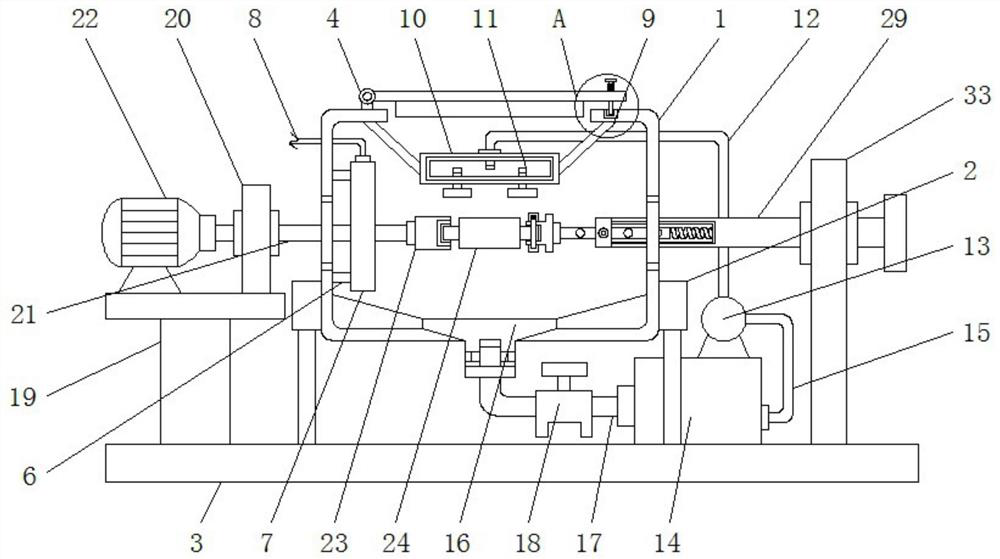
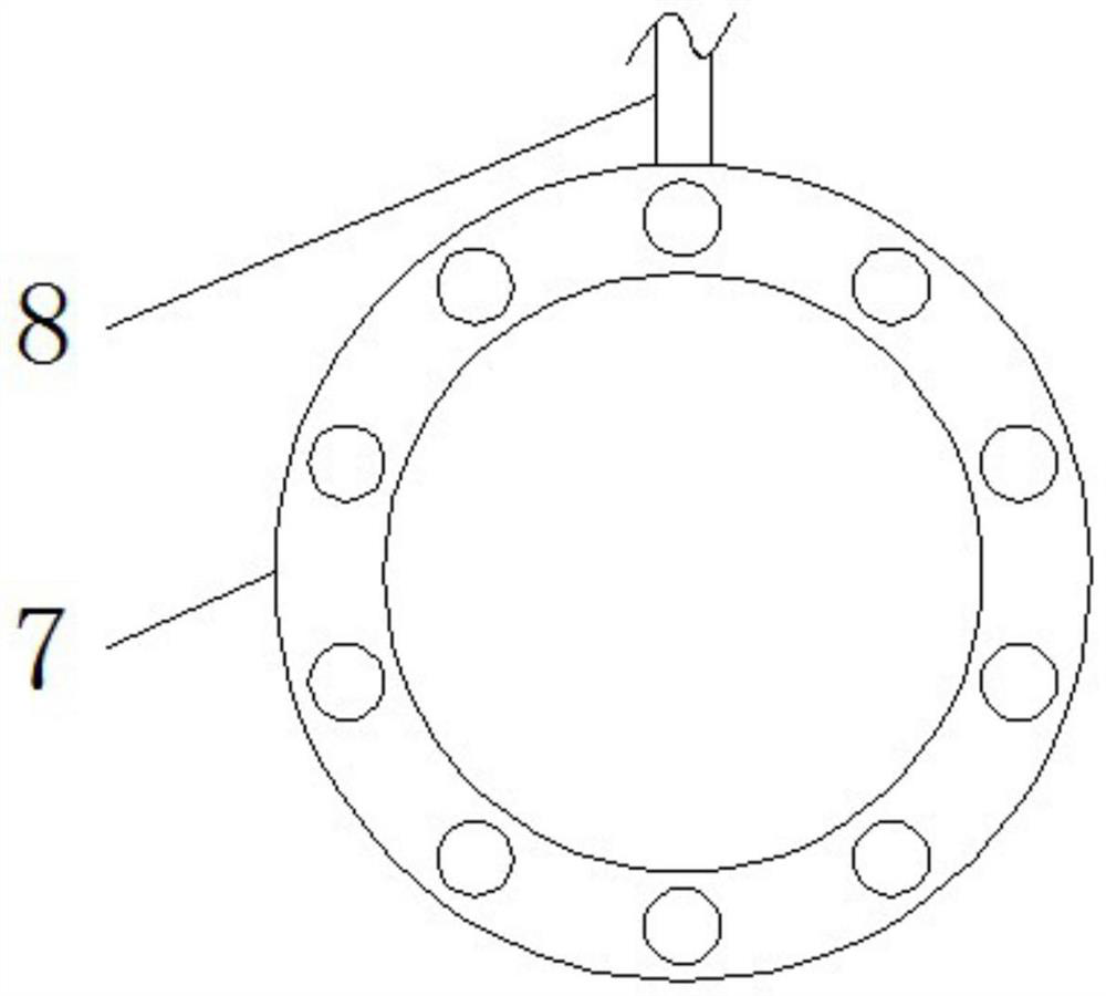
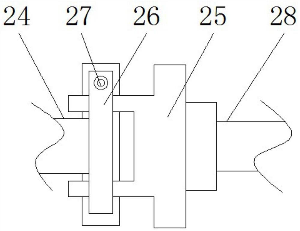
[0029] see Figure 1-5, a spraying equipment for aviation parts, comprising a spraying box 1, the bottom of the side of the spraying box 1 is fixedly connected with the top of the base 3 through a support rod 2, and one side of the top of the spraying box 1 is fixedly installed with a movable cover 4, and the movable cover 4 One side of the top is movably connected with the other side of the top of the spraying box 1 through a fixing device 5. The fixing devic...


PUM


Abstract

The invention relates to the technical field of space flight and aviation, and discloses spraying equipment for aeronautical parts. The spraying equipment comprises a spraying box, wherein the bottomof the side face of the spraying box is fixedly connected with the top of a base through supporting rods, a movable cover is fixedly mounted at one side of the top of the spraying box, one side of thetop of the movable cover is movably connected with the other side of the top of the spraying box through a fixing device, the side face of an inner cavity of the spraying box is fixedly connected with one side of a heating plate through connecting blocks, a power line is fixedly connected to the top of the heating plate, and the top of the inner cavity of the spraying box is fixedly connected with the side face of a conveying pipe through connecting rods. According to the spraying equipment for the aeronautical parts, through cooperation of a rotating rod, a motor, a clamping block, a fixture, an adjusting rod and a movable rod, the parts can be driven by the rotating rod to rotate in the spraying process, so that the surfaces of the parts are subjected to uniform spraying, the working intensity of operators is lowered, the spraying speed is increased, and the working efficiency of part spraying is improved.

Description

technical field [0001] The invention relates to the field of aerospace technology, in particular to a spraying equipment for aviation parts. Background technique [0002] Aeronautical parts refer to inseparable single parts in aviation machinery, which are the basic components of the machine and the basic unit in the manufacturing process of aviation machinery, such as bushings, nuts, blades, gears, cams and connecting rods, etc., and In the process of using aviation parts, in order to improve the corrosion resistance and high temperature resistance of aviation parts, it is necessary to use spraying equipment to spray the surface during the production and processing of aviation parts. [0003] However, the existing spraying equipment for aviation parts can only spray the surface of the part facing the position of the nozzle during the spraying process, and it is necessary to manually adjust the position of the part to fully spray the surface of the part, which not only incre...

Claims


Application Information

Patent Timeline
Patent Type & Authority Applications(China)
IPC IPC(8): B05B16/20B05B14/00B05B13/02
CPCB05B13/0228B05B14/00B05B16/20
Inventor 刘毅峰
Owner 杭州彩兔贸易有限公司
Why Eureka
Try Eureka