
Power cable pipeline cleaning device and using method thereof

A technology for cleaning devices and power cables, applied in the directions of cleaning methods and utensils, spray devices, chemical instruments and methods, etc., can solve the problems of secondary pollution, dust dissipation, cable core damage, etc., to avoid damage and dust escape. , the effect of avoiding secondary pollution

Active Publication Date: 2020-12-08
湖南申龙电力勘测设计有限公司
View PDF9 Cites 2 Cited by
  • Summary
  • Abstract
  • Description
  • Claims
  • Application Information

AI Technical Summary

Problems solved by technology

[0002] The cable pipe is used to install the pipe for passing the cable. In the cable installation project, the cable pipe must first be installed in the excavated foundation pit. There may be mud at any time during the transportation, handling and installation of the pipe. Sand, gravel or concrete slurry enters the pipeline. When there are concrete agglomerates or gravel and other debris inside the pipeline, the cables are passed through the pipeline, and the impurities may scratch the outer sheath of the cable, causing the cable heart is damaged
[0003] In the prior art, the invention patent with the patent application number 201621288588.6 discloses "a cable pipe cleaning device; the technical problem to be solved: the technical defect of the poor pipe passing effect of the pipe passer in the prior art mentioned in the background technology
The present invention has the advantage of cleaning, but there are still defects. When a cable is placed in the pipe, the work will be affected. At the same time, the dust in the process of scraping the mud by the scraper will escape, which will easily cause secondary pollution.

Method used


Image

  • Power cable pipeline cleaning device and using method thereof
  • Power cable pipeline cleaning device and using method thereof
  • Power cable pipeline cleaning device and using method thereof

Examples


Embodiment 1

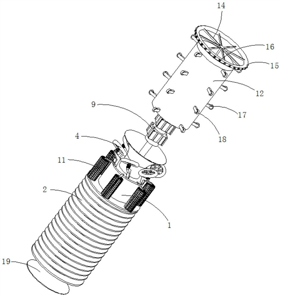
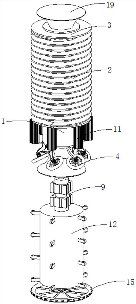
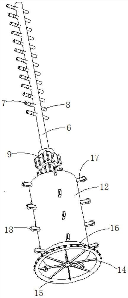
[0039] refer to Figure 1-8, a power cable duct cleaning device, including an installation cylinder 1, the installation cylinder 1 includes a hollow part 101 and a sealing part 102, the outer wall of the hollow part 101 is fixed with a shoveling piece 2 arranged in a spiral, and the two ends of the shoveling piece 2 It is also fixedly connected with the limit plate 3 set on the outer wall of the hollow part 101, and the outer wall of the sealing part 102 is provided with evenly distributed cleaning components. 4. A sealing cylinder 5 is rotatably connected to the installation cylinder 1, and the inner cavity of the sealing cylinder 5 is provided with a negative pressure air pipe 6, and the negative pressure air pipe 6 is provided with a uniformly distributed first dust removal pipe 7 and a second dust removal pipe 8. One end of a cleaning pipe 7 away from the negative pressure air pipe 6 is placed in the inner cavity between the sealing cylinder 5 and the installation cylinder...

Embodiment 2

[0046] refer to Figure 6-7 , a power cable duct cleaning device, which is basically the same as that of Embodiment 1, and furthermore, the thickness of the outer edge of the shovel sheet 2 is greater than the thickness of the joint between the shovel sheet 2 and the hollow part 101, so as to avoid the agglomeration of the removed concrete. In the gaps of the shovel sheet 2, the stability of the shovel is improved.

Embodiment 3

[0048] refer to Figure 1-7 , a power cable duct cleaning device, including an installation cylinder 1, the installation cylinder 1 includes a hollow part 101 and a sealing part 102, the outer wall of the hollow part 101 is fixed with a shoveling piece 2 arranged in a spiral, and the two ends of the shoveling piece 2 It is also fixedly connected with the limit plate 3 set on the outer wall of the hollow part 101, and the outer wall of the sealing part 102 is provided with evenly distributed cleaning components. 4. A sealing cylinder 5 is rotatably connected to the installation cylinder 1, and the inner cavity of the sealing cylinder 5 is provided with a negative pressure air pipe 6, and the negative pressure air pipe 6 is provided with a uniformly distributed first dust removal pipe 7 and a second dust removal pipe 8. One end of a cleaning pipe 7 away from the negative pressure air pipe 6 is placed in the inner cavity between the sealing cylinder 5 and the installation cylinde...


PUM


Abstract

The invention discloses a power cable pipeline cleaning device and a using method thereof, and belongs to the technical field of cable pipeline cleaning. The power cable pipeline cleaning device comprises a mounting cylinder, wherein the mounting cylinder comprises a hollow part and a sealing part; the outer side wall of the hollow part is fixedly connected with a spirally arranged shoveling piece; the two ends of the shoveling piece are further fixedly connected with limiting plates which are arranged on the outer wall of the hollow part in a sleeving manner; uniformly distributed cleaning assemblies are arranged on the outer side wall of the sealing part; one side, far away from the hollow part, of the sealing part is connected with an obliquely arranged self-driving wheel through a bracket; a sealing cylinder is rotationally connected in the mounting cylinder; and a negative pressure air pipe is arranged in an inner cavity of the sealing cylinder. According to the power cable pipeline cleaning device and the using method thereof, the function of centralized shoveling of concrete blocks and sand stones on the inner wall of a pipeline and the function of cleaning the pipe wall ofthe shoveled cable pipeline are realized, an anti-oxidation paint layer is sprayed on the inner wall of the cleaned pipeline, and the function of centralized collection of dust-containing gas is realized while the function of repairing an anti-oxidation layer on the inner wall of the shoveled pipeline is realized.

Description

technical field [0001] The invention relates to the technical field of cable duct cleaning, in particular to a power cable duct cleaning device and a method for using the same. Background technique [0002] The cable pipe is used to install the pipe for passing the cable. In the cable installation project, the cable pipe must first be installed in the excavated foundation pit. There may be mud at any time during the transportation, handling and installation of the pipe. Sand, gravel or concrete slurry enters the pipeline. When there are concrete agglomerates or gravel and other debris inside the pipeline, the cables are passed through the pipeline, and the impurities may scratch the outer sheath of the cable, causing the cable The heart is damaged. [0003] In the prior art, the invention patent with the patent application number 201621288588.6 discloses "a cable pipe cleaning device; the technical problem to be solved: the technical defect of the poor pipe passing effect o...

Claims


Application Information

Patent Timeline
Patent Type & Authority Applications(China)
IPC IPC(8): B08B9/051B08B15/04B08B13/00B05B13/06
CPCB08B9/051B08B15/04B08B13/00B05B13/06
Inventor 王涛吴鑫陈士涛
Owner 湖南申龙电力勘测设计有限公司
Learn More