Metal bending equipment of automatic discharging mechanism for metal bending

An automatic cutting and metal technology, applied in the field of metal bending, can solve the problems of increasing manual workload and operation complexity, increasing bending time, employee and company losses, etc., to reduce manual cutting time, The effect of reducing collision sound and improving work efficiency

Inactive Publication Date: 2020-12-08
谭静
View PDF8 Cites 1 Cited by
  • Summary
  • Abstract
  • Description
  • Claims
  • Application Information

AI Technical Summary

Problems solved by technology

[0003] However, today's thicker metal sheet metal bending equipment is all manually loaded and bent, and then manually unloaded, which not only increases the manual workload and operational complexity, but also increases the cost of a thick metal sheet. Bending forming time and reduced work efficiency are a loss for employees and the company

Method used


Image

  • Metal bending equipment of automatic discharging mechanism for metal bending
  • Metal bending equipment of automatic discharging mechanism for metal bending
  • Metal bending equipment of automatic discharging mechanism for metal bending

Examples


Embodiment 1

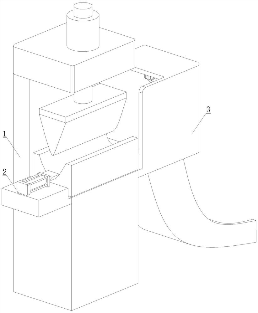
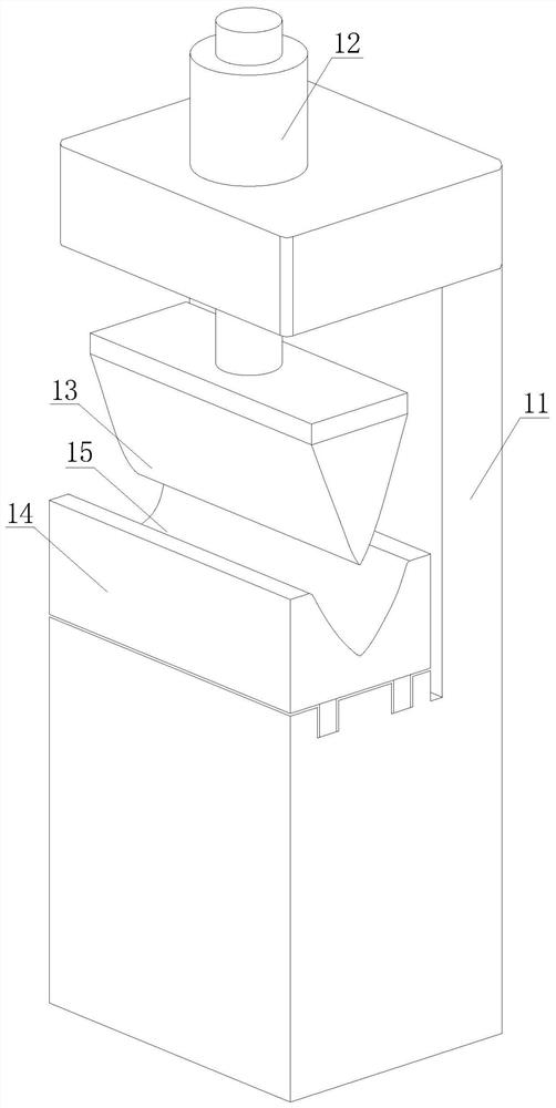
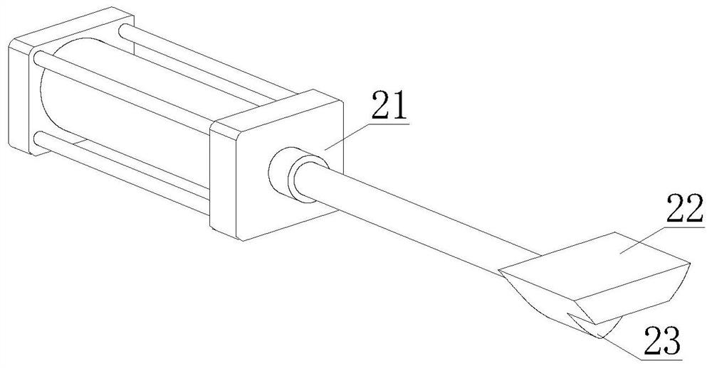
[0032] see Figure 1-2 , a metal bending equipment with an automatic blanking mechanism for metal bending, including a bending host 1, a blanking mechanism 2, a material guide mechanism 3 and a forming block 4, and the blanking mechanism 2 is arranged on one side of the bending host 1 At the upper end, the material guide mechanism 3 is set on the upper end of the other side of the bending main machine 1 corresponding to the unloading mechanism 2, and the forming block 4 is set on the upper end of the bending main machine 1. The bending main machine 1 includes a chassis 11, a hydraulic cylinder 12, and a pressure head. 13. The pressure bearing block 14 and the pressure groove 15, the hydraulic cylinder 12 runs through the upper middle of the chassis 11, the upper middle of the pressure head 13 is set at the lower end of the hydraulic cylinder 12, the pressure bearing block 14 is placed on the inner upper end of the chassis 11, and the pressure groove 15 Opened on the upper end ...

Embodiment 2

[0037] see Figure 1-3 , a metal bending equipment with an automatic blanking mechanism for metal bending, including a bending host 1, a blanking mechanism 2, a material guide mechanism 3 and a forming block 4, and the blanking mechanism 2 is arranged on one side of the bending host 1 At the upper end, the material guide mechanism 3 is set on the upper end of the other side of the bending main machine 1 corresponding to the unloading mechanism 2, and the forming block 4 is set on the upper end of the bending main machine 1. The bending main machine 1 includes a chassis 11, a hydraulic cylinder 12, and a pressure head. 13. The pressure bearing block 14 and the pressure groove 15, the hydraulic cylinder 12 runs through the upper middle of the chassis 11, the upper middle of the pressure head 13 is set at the lower end of the hydraulic cylinder 12, the pressure bearing block 14 is placed on the inner upper end of the chassis 11, and the pressure groove 15 Opened on the upper end ...


PUM


Abstract

The invention discloses metal bending equipment of an automatic discharging mechanism for metal bending. The metal bending equipment comprises a bending main machine, a discharging mechanism, a material guiding mechanism and a forming block, one end of an upper stop block and one end of a lower push block are fixedly connected with the output end of a long-strip air cylinder in a threaded mode, the upper stop block is located at the upper end of the lower push block, and automatic discharging of the forming block is achieved. The manual discharging time of an operator is shortened, and the working efficiency of the metal bending equipment is improved. The lower end of a roller is lower than the lower end of the forming block. After the forming block is pushed, the lower end of the formingblock impacts the roller, the forming block changes the direction and moves downwards obliquely under the action of self gravity and residual inertia, and first-time direction-changing discharging ofthe forming block is achieved. The inclined falling point of the bottom end of the forming block is located in the middle of the upper end of a fixing piece, when the forming block falling from a material guiding box impacts the fixing piece, the material guiding box has a certain inclination angle, the buffering effect of a second buffering spring wire is matched, so that the forming block changes the direction for the second time, discharging is slow, and manual operation is not needed.

Description

technical field [0001] The invention relates to the technical field of metal bending, in particular to a metal bending equipment with an automatic unloading mechanism for metal bending. Background technique [0002] Bending (Bending) - metal sheet under the pressure of the upper or lower die of the bending machine, first undergoes elastic deformation, and then enters plastic deformation. In the initial stage of plastic bending, the sheet is free to bend. When the lower mold exerts pressure on the sheet, the sheet and the inner surface of the V-groove of the lower mold gradually get closer, and at the same time, the radius of curvature and the bending arm also gradually become smaller. Continue to pressurize until the stroke ends, so that the upper and lower molds and the sheet are in three-point contact. Tight full contact, a V-shaped bend is completed at this time, which is commonly known as bending; metal bending operations are an essential part of many manufacturing proce...

Claims


Application Information

Patent Timeline
Patent Type & Authority Applications(China)
IPC IPC(8): B21D5/01B21D45/00B21D55/00
CPCB21D5/01B21D45/00B21D55/00
Inventor 谭静
Owner 谭静
Why Eureka
Try Eureka