
Composite cable clamp stamping tool and stamping method thereof

A cable clamp and composite technology, which is applied in the field of composite cable clamp stamping tooling and stamping, can solve the problems of poor clamp uniformity, time-consuming and labor-intensive, high production costs, etc., to achieve rapid stamping and forming, ensure the quality of the forming, and prolong the service life The effect of longevity

Active Publication Date: 2020-12-08
BEIJING HANGXING MACHINERY MFG CO LTD
View PDF5 Cites 0 Cited by
  • Summary
  • Abstract
  • Description
  • Claims
  • Application Information

AI Technical Summary

Problems solved by technology

[0003] In view of the above analysis, the present invention aims to provide a composite cable clamp stamping tool and its stamping method to solve the problems of time-consuming and labor-intensive production process, poor clamp uniformity and high production cost.

Method used


Image

  • Composite cable clamp stamping tool and stamping method thereof
  • Composite cable clamp stamping tool and stamping method thereof
  • Composite cable clamp stamping tool and stamping method thereof

Examples


Embodiment 1

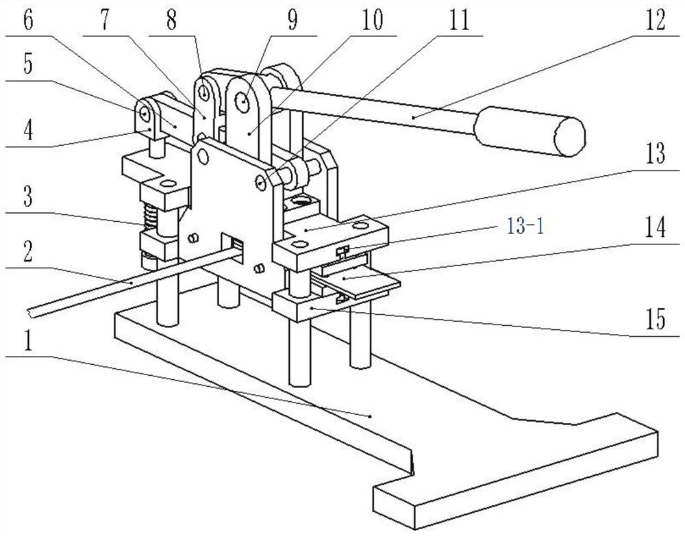
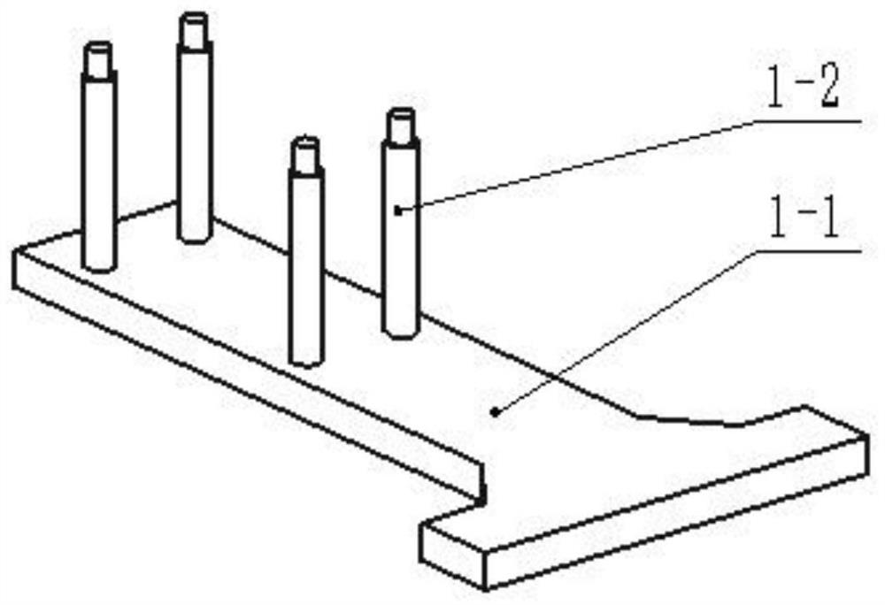
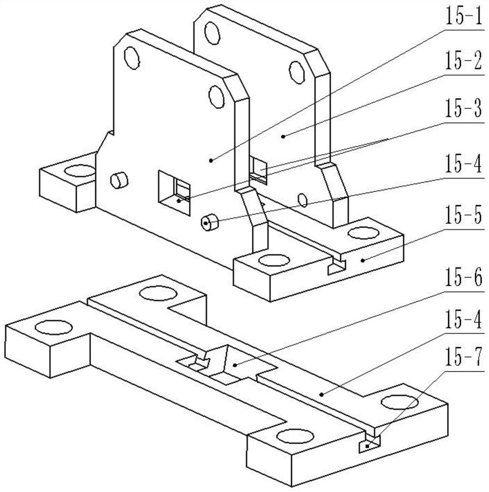
[0044] A specific embodiment of the present invention discloses a composite cable clamp stamping tool, such as Figure 1-8 As shown, it includes: a base 1, a connecting rod mechanism, a reset mechanism, a fixed plate 13, a composite stamping die 14 and a bracket 15;

[0045] Wherein, the composite stamping die 14 includes: a first die 14-1 and a second die 14-5. Outer arc punches 14-1-1, outer arc punching grooves 14-1-5, and round hole punches that are respectively arranged on the corresponding positions of the first mold 14-1 and the second mold 14-5 14-1-4, round hole punching groove 14-1-6, its shape and size specifications are consistent with the specifications of the outer arc edge 2-1 of the cable clamp, and the specifications of the nail hole 2-2; that is to say, the stamping process of the composite stamping die 14 Among them, the outer arc punch 14-1-1 and the outer arc punching groove 14-1-5 cooperate to punch out the outer arc edge 2-1 on one side of the cable cla...

Embodiment 2

[0083] This embodiment provides a stamping method of the composite cable clamp stamping tool of the present invention, using the composite cable clamp stamping tool of Embodiment 1 to stamp and form the cable clamp, which specifically includes the following steps:

[0084] S1: Install the composite stamping die 14 on the stamping tool; send the material 2 into the stamping tool through the inlet and outlet 15-3;

[0085] S2: Press down the pressure rod 12 to close the first mold 14-1 and the second mold 14-5 to stamp the material 2; loosen the pressure rod 12 to reset the stamping tool; the first stamping is completed, and the cable clamp is obtained unilateral outer arc edge 2-1 and nail hole 2-2;

[0086] S3: Push the material 2 forward to move the length of the distance cable clamp; press down the pressure rod 12, and the composite stamping die 14 punches out the outer arc edge 2-1 and the nail hole 2-2 on the other side of the clamp and the lower One-side outer arc edge 2...


PUM


Abstract

The invention relates to a composite cable clamp stamping tool and a stamping method thereof, belongs to the technical field of mechanical manufacturing equipment, and solves problems of time and labor waste in the clamp manufacturing process, poor clamp uniformity and high production cost in the prior art. A composite stamping mold of the composite cable clamp stamping tool is provided with a first mold and a second mold which can move relatively, the first mold and the second mold are provided with multiple sets of stamping units, an outer arc punch and a round hole punch of the first mold are matched with an outer arc punching groove and a round hole punching groove of the second mold to achieve stamping of a cable clamp, the first mold and the second mold of the composite stamping moldare driven by a connecting rod mechanism to perform stamping, and reset is conducted through a reset spring after stamping is completed. According to the composite cable clamp stamping tool, clamps of different models can be manufactured, repeated disassembly and assembly of molds are not needed, raw materials are saved, the uniformity and the quality reliability of the clamps are improved, and the production cost is reduced.

Description

technical field [0001] The invention relates to the technical field of mechanical manufacturing equipment, in particular to a composite cable clamp punching tool and a punching method thereof. Background technique [0002] Cable laying is an important part of the manufacturing of aviation products. At present, aluminum alloy or stainless steel cable clamps are often used to lay and bind cables. In the specific construction process, for the cables that need to be fixed, it is often necessary to specially make cable clamps that meet the design requirements according to the construction progress, cable diameter, and site conditions. The difference of the cable clamp is that the size of the screw hole is different and the length of the cable clamp is different. In the existing technology, in the process of making cable clamps, due to the influence of their specifications, quantities, materials, etc., manual cutting is often used for production. production cost of the enterpris...

Claims


Application Information

Patent Timeline
IPC IPC(8): B21D35/00B21D28/02B21D28/20B21D28/26B21D37/08
CPCB21D35/001B21D35/002B21D28/002B21D28/02B21D28/20B21D28/26B21D37/08
Inventor 高军赵小飞王鸿熠朱宝贤任立鹏
Owner BEIJING HANGXING MACHINERY MFG CO LTD
Learn More