Remote control electric insulation clamp

A technology of insulating clamps and clamps, which is applied in the direction of clamps, overhead line/cable equipment, hand-held tools, etc., which can solve the problems that the wires cannot be clamped, time-consuming and labor-intensive, and the direction of the head of the insulating clamp cannot be adjusted freely. , to achieve the effect of reliable action, light weight and compact structure

Pending Publication Date: 2020-12-08
杭州贝特设备制造有限公司
View PDF1 Cites 2 Cited by
  • Summary
  • Abstract
  • Description
  • Claims
  • Application Information

AI Technical Summary

Problems solved by technology

[0003] 1. The existing insulating clamps are basically purely mechanical and manual. For example, the screw clamping operation is time-consuming and labo

Method used


Image

  • Remote control electric insulation clamp
  • Remote control electric insulation clamp
  • Remote control electric insulation clamp

Examples


Example Embodiment

[0038] Example 1, see Figure 1-9 shown.

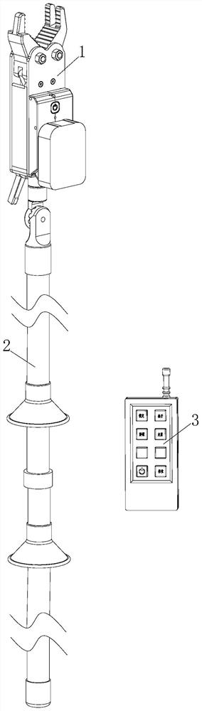
[0039] The remote control electric insulating clamp in this embodiment includes an insulating clamp main body 1, an insulating operating rod 2 and a remote control 3, the insulating clamp main body 1 is installed on the insulating operating rod 2, and the insulating clamp main body 1 is connected to the remote control 3 .

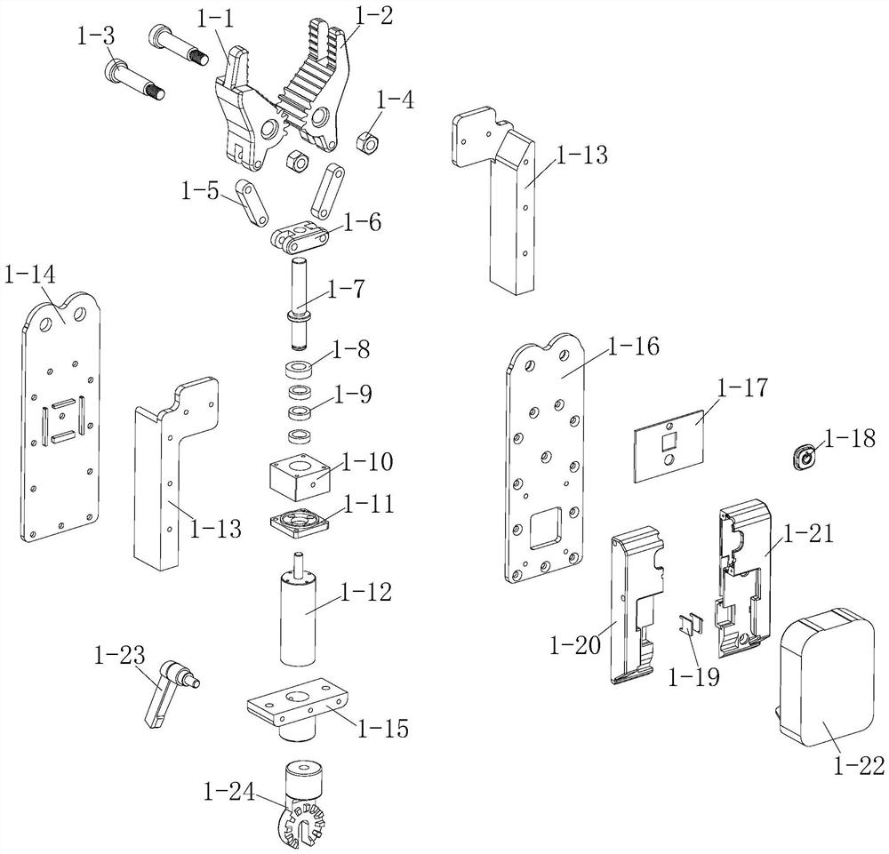
[0040] The main body 1 of the insulating clamp in this embodiment includes a collet, a collet driving mechanism, screws 1-3, nuts 1-4, a main body spacer 1-13, a left side plate 1-14, and a torx head connection seat 1-15 , right side board 1-16, main control circuit board 1-17, button cap 1-18, power contact piece 1-19, clamp female shell 1-20, clamp male shell 1-21, power supply 1-22, Thumb screw 1-23 and Torx head 1-24.

[0041] The collet in this embodiment is connected with the collet driving mechanism, and the collet includes a male tongs 1-1 and a female tongs 1-2, a male tongs 1-1 and a female tongs 1 -2...

Example Embodiment

[0058] Example 2 (flat type), see figure 2 , 3 and 7-12.

[0059] The remote control electric insulating clamp in this embodiment includes an insulating clamp main body 1, an insulating operating rod 2 and a remote control 3, the insulating clamp main body 1 is installed on the insulating operating rod 2, and the insulating clamp main body 1 is connected to the remote control 3 .

[0060] The main body 1 of the insulating clamp in this embodiment includes a collet, a collet driving mechanism, screws 1-3, nuts 1-4, a main body spacer 1-13, a left side plate 1-14, and a torx head connection seat 1-15 , right side board 1-16, main control circuit board 1-17, button cap 1-18, power contact piece 1-19, clamp female shell 1-20, clamp male shell 1-21, power supply 1-22, Thumb screw 1-23 and Torx head 1-24.

[0061] The collet in this embodiment is connected with the collet driving mechanism, and the collet includes a male tongs 1-1 and a female tongs 1-2, a male tongs 1-1 and a ...


PUM


Abstract

The invention relates to a remote control electric insulation clamp and belongs to the field of distribution network hot-line work equipment. The remote control electric insulation clamp comprises aninsulation clamp main body, an insulation operating rod and a remote controller, wherein the insulation clamp main body is installed on the insulation operating rod and is connected with the remote controller, the remote control electric insulation clamp is structurally characterized in that the insulation clamp main body comprises a chuck and a chuck driving mechanism, the chuck is connected withthe chuck driving mechanism, the chuck comprises a clamp male chuck and a clamp female chuck, the clamp male chuck and the clamp female chuck are both connected with the chuck driving mechanism, thechuck driving mechanism comprises connecting rods and a push block, the clamp male chuck and the clamp female chuck are each connected with one connecting rod, the two connecting rods are both connected with the push block, and/or the clamp male chuck and the clamp female chuck are provided with clamp male chuck meshing teeth and clamp female chuck meshing teeth respectively, and the clamp male chuck meshing teeth are meshed with the clamp female chuck meshing teeth.

Description

technical field [0001] The invention relates to a remote-controlled electric insulating clamp, which belongs to the field of distribution network live working equipment. Background technique [0002] It is often necessary to clamp the wires during live work in the distribution network. The existing clamping tools often have the following disadvantages: [0003] 1. The existing insulating clamps are basically purely mechanical and manual. For example, the operation of the screw clamping type is time-consuming and laborious. [0004] 2. The basic head direction of existing insulating clamps cannot be adjusted freely, resulting in failure to clamp vertical or oblique wires. [0005] In view of this, a remote control split-type locking wire clamp is disclosed in the patent document with the application number 201711227669.4. Although the content disclosed in the reference document also realizes the wire clamping function, its structure is different from that of the present appl...

Claims


Application Information

Patent Timeline
IPC IPC(8): B25B5/04B25B5/06B25B5/16B25G1/04B25G1/12H02G1/02
CPCB25B5/04B25B5/06B25B5/16B25G1/04B25G1/12H02G1/02B25B5/10B25B5/12B25B5/163
Inventor 阮关有沈海华山建冬吴世军周光辉
Owner 杭州贝特设备制造有限公司
Why Eureka
Try Eureka