Air-ground dual-purpose unmanned aerial vehicle
A UAV, dual-use technology, applied in the field of UAVs, can solve the problems of low distribution efficiency, high distribution risk factor, and restrictions on UAV distribution application scenarios.
- Summary
- Abstract
- Description
- Claims
- Application Information
AI Technical Summary
Problems solved by technology
Method used
Image

Examples
Embodiment Construction
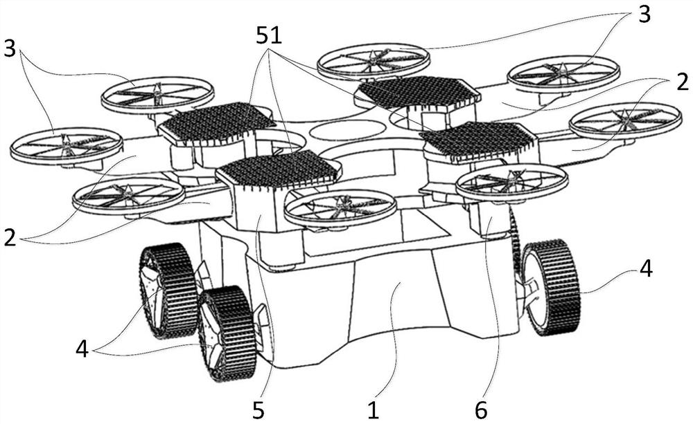
[0042] The core of the present invention is to provide an air-ground dual-purpose unmanned aerial vehicle, which can fly in the air and walk on the ground, can be applied to uneven ground, and has strong adaptability.
[0043] In order to enable those skilled in the art to better understand the technical solution of the present invention, the air-ground dual-purpose UAV of the present invention will be described in detail below in conjunction with the accompanying drawings and specific implementation methods.
[0044] Such as figure 1 As shown, it is an axonometric schematic diagram of a specific embodiment of the air-ground dual-purpose drone provided by the present invention; the air-ground dual-purpose drone of the present invention includes a fuselage 1, and the fuselage 1 is the main part of the entire drone. Install other components thereon; the fuselage 1 is provided with a foldable flight support 2, the flight support 2 can be stretched and folded relative to the fusel...
PUM
 Abstract
Description
Claims
Application Information
 - R&D
- Intellectual Property
- Life Sciences
- Materials
- Tech Scout
- Unparalleled Data Quality
- Higher Quality Content
- 60% Fewer Hallucinations
Browse by: Latest US Patents, China's latest patents, Technical Efficacy Thesaurus, Application Domain, Technology Topic, Popular Technical Reports.
© 2025 PatSnap. All rights reserved.Legal|Privacy policy|Modern Slavery Act Transparency Statement|Sitemap|About US| Contact US: help@patsnap.com