Eureka AIR delivers breakthrough ideas for toughest innovation challenges, trusted by R&D personnel around the world.

Wallpaper blade coating mechanism for wallpaper production line

A production line and wallpaper technology, applied in the field of wallpaper scraping mechanism for wallpaper production line, can solve the problems of paint splashing, poor coating thickness uniformity and high cost, and achieve the effects of easy processing and installation, reduction of paint waste, and simple and reasonable structure.

Pending Publication Date: 2020-12-08
天津市艺恩装饰材料有限公司
View PDF0 Cites 1 Cited by
  • Summary
  • Abstract
  • Description
  • Claims
  • Application Information

AI Technical Summary

Problems solved by technology

[0003] The wallpaper production process includes at least the steps of base paper sending, coating, drying, cooling, printing, drying, film lamination, drying, and winding. Among them, the coating operation is mostly performed by specific coating equipment, which has a complex structure and high cost. , and the existing coating equipment still has the problems of poor uniformity of coating thickness and inconvenient adjustment of coating thickness when performing coating coating, which affects the quality of wallpaper production
[0004] In addition, when using roller coating equipment for coating, due to the rotation of the coating roller, the problem of paint splashing will also be caused, which not only causes waste of paint, but also affects the overall production environment

Method used

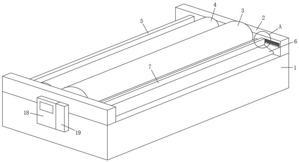
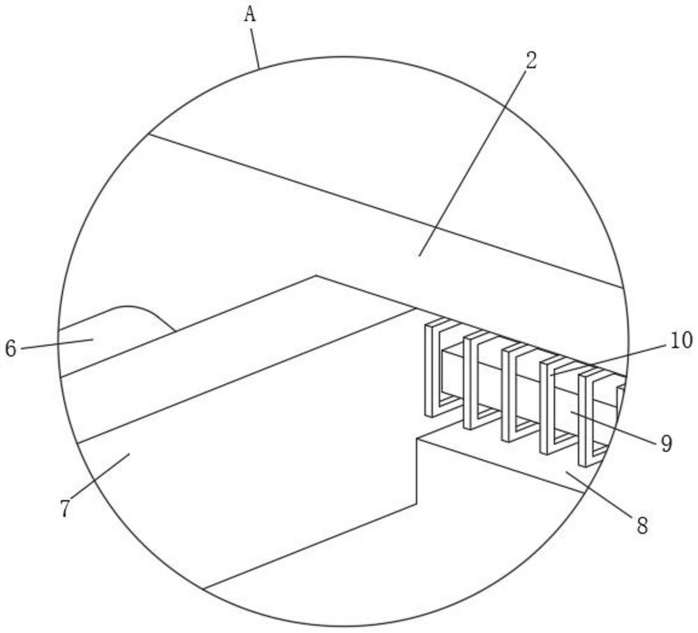

Image

  • Wallpaper blade coating mechanism for wallpaper production line
  • Wallpaper blade coating mechanism for wallpaper production line
  • Wallpaper blade coating mechanism for wallpaper production line

Examples


Embodiment 1

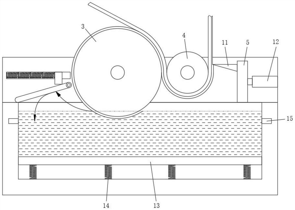
[0059] see Figure 3-Figure 4 As shown, the lifting drive assembly includes at least one lifting spring 14 , and the lifting piston plate 13 is welded to the top of the lifting spring 14 .

[0060] Specifically, in this embodiment, based on the weight (gravity) of the paint stored in the material storage box 1 and the elastic force of the lifting spring 14 to form a support balance; in the continuous scraping process, the paint in the material storage box 1 gradually decreases, and the corresponding weight (Gravity) descends, thereby support balance is destroyed, elastic force>gravity, realizes the rising of lifting piston plate 13; Thus, the lifting drive of the lifting piston plate 13 can be effectively satisfied.

Embodiment 2

[0062] see Figure 5 As shown, the lifting drive assembly includes a second electric push rod 16 and a liquid level sensor 17, the lifting piston plate 13 is fixed on the top of the second electric push rod 16, the liquid level sensor 17 is embedded on the inner wall of the material storage box 1, and the liquid level sensor The height of 17 is higher than coating roller 3 bottoms.


PUM


Abstract

The invention belongs to the technical field of wallpaper production, and discloses a wallpaper blade coating mechanism for a wallpaper production line. The wallpaper blade coating mechanism comprisesa material storage box with an open top, wherein two fixed side plates are symmetrically welded to the top of the material storage box; a coating roller which is rotationally installed between the two fixed side plates, wherein the bottom of the coating roller is located in the storage box; a pressing roller which is rotationally installed between the two fixed side plates and located on one sideof the coating roller, wherein the bottom of the pressing roller is located above the storage box; and a movable scraper which is arranged between the two fixed side plates in a sliding mode, whereinpressing roller is located between the scraper and the coating roller, and wallpaper sequentially penetrates through the gap between the coating roller and the pressing roller and the gap between thepressing roller and the scraper in the coating process; in conclusion, uniform coating of the wallpaper is effectively achieved based on the arrangement of the coating roller, the pressing roller andthe scraper, the coating thickness of the coating can be effectively adjusted, and the wallpaper blade coating mechainsm has the advantages of being simple and reasonable in structure, low in cost and convenient to machine and install.

Description

technical field [0001] The invention belongs to the technical field of wallpaper production, and in particular relates to a wallpaper scraping mechanism for a wallpaper production line. Background technique [0002] As a decorative material with cultural color, wallpaper is mainly used to beautify indoor walls and ceilings. It has the advantages of various designs and colors, wide application range, moderate price, sound insulation, heat insulation, scrub resistance, easy replacement, and strong three-dimensional effect. . [0003] The wallpaper production process includes at least the steps of base paper sending, coating, drying, cooling, printing, drying, film lamination, drying, and winding. Among them, the coating operation is mostly performed by specific coating equipment, which has a complex structure and high cost. , and the existing coating equipment also has the problems of poor uniformity of coating thickness and inconvenient adjustment of coating thickness when p...

Claims


Application Information

Patent Timeline
IPC IPC(8): D21H27/20D21H23/56D21H23/34
CPCD21H27/20D21H23/56D21H23/34
Inventor 吴伦书
Owner 天津市艺恩装饰材料有限公司
Why Eureka
Eureka Blog
Learn More