
Optical film, anti-reflection film, polarizing plate and image display device

a technology of anti-reflection film and optical film, which is applied in the direction of polarizing elements, instruments, transportation and packaging, etc., can solve the problems of low surface free energy of a coated film formed after drying, difficult to maintain solvent drying, and uneven drying. , to achieve the effect of reducing drying unevenness, high surface uniformity and sufficient scratch resistan

Inactive Publication Date: 2007-09-06
FUJIFILM CORP
View PDF7 Cites 34 Cited by
  • Summary
  • Abstract
  • Description
  • Claims
  • Application Information

AI Technical Summary

Benefits of technology

[0012](1) an optical film which achieves both high surface uniformity with decreasing drying unevenness and wind unevenness and sufficient scratch resistance,
[0013](2) an antireflection film which achieves both sufficient anti-reflection ability and scratch resistance in addition to surface uniformity,
[0014](3) a high-speed coating production process which enable to obtain the above antireflection film with high productivity, and
[0016]The inventors have found that a coating composition can be obtained which can be uniformly coated, which can reduce drying non-uniformity and non-uniformity in thickness caused by drying air, and which ensures film hardness, by using a thickening agent that satisfies specific thickening performance and using as the thickening agent a thixotropic agent or a high molecular polymer having a mass-average molecular mass of from 500,000 to 5,000,000 in terms of polystyrene (hereinafter referred to as “ultra-high molecular mass polymer”). The inventors have also found that an optical film (particularly, anti-reflection film) which does not generate white glistening upon a thickening agent being used can be obtained by controlling the particle size of fine particles and the film thickness within appropriate ranges. Further, the inventors have found a novel process for producing an anti-reflection film having a high surface uniformity with a high productivity by using a coating composition containing the above-mentioned thickening agent and coating plural layers at the same time.

Problems solved by technology

However, although the all-wet coating using a solvent is extremely advantageous in view of productivity, it is extremely difficult to maintain drying of the solvent immediately after coating at a constant level, and there tends to result surface non-uniformity.
However, although a uniform film is formed due to leveling effect by adding a surfactant to a coating composition, the surface free energy of a coated film formed after drying becomes so low that there have been problems that, when the surface is stuck onto other material or when the surface is further coated, adhesion at the interface becomes weak and scratch resistance is deteriorated.
Also, in the case of adding a thickening agent, addition of a large amount of the thickening agent is required in order to obtain a desired viscosity and, as a result, there has been a problem that the film hardness is decreased.
Further, when a thickening agent is added in a large amount to a coating composition containing fine particles for forming an anti-glare film, there has been involved a problem that the surface glistens white all over in a bright room (hereinafter referred to as “white glistening”) in the case of applying the anti-glare film to the surface of a display device.

Method used

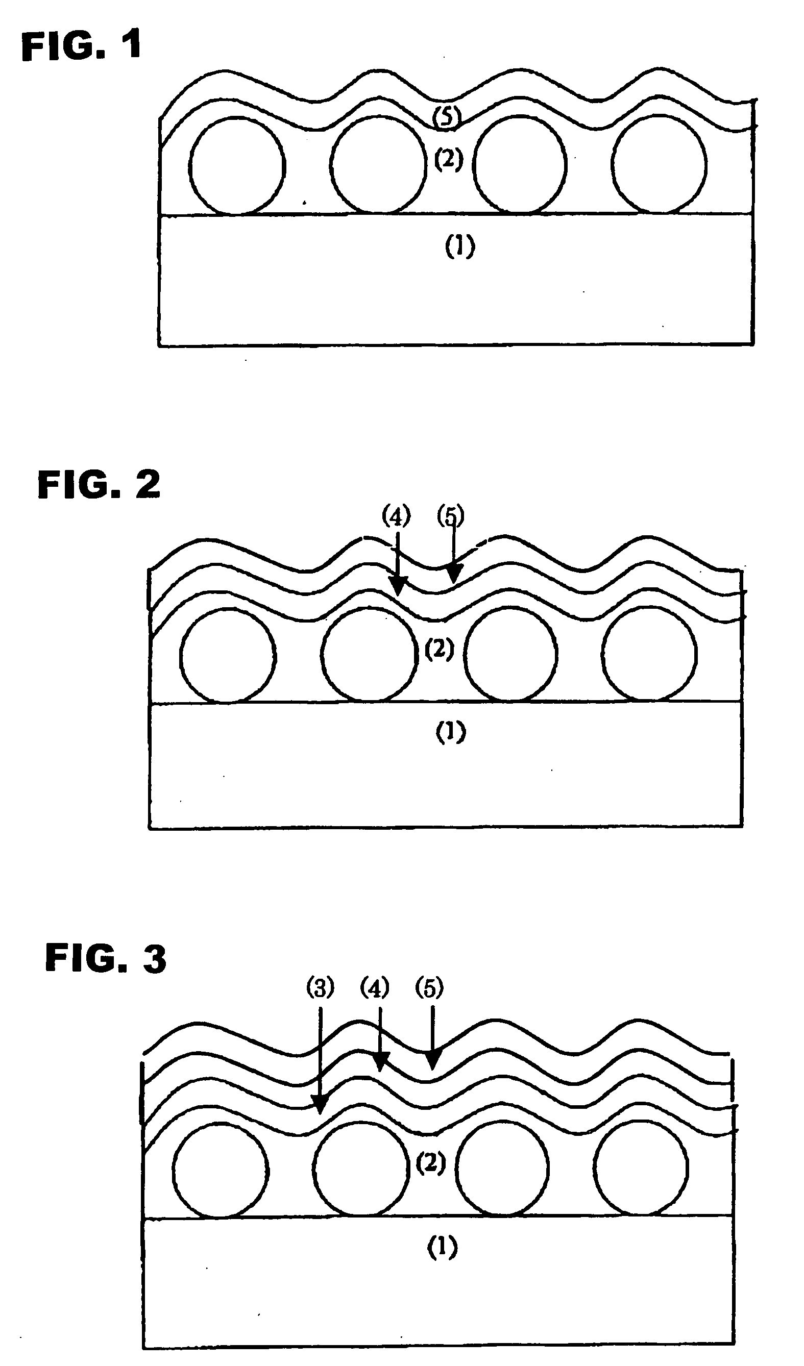
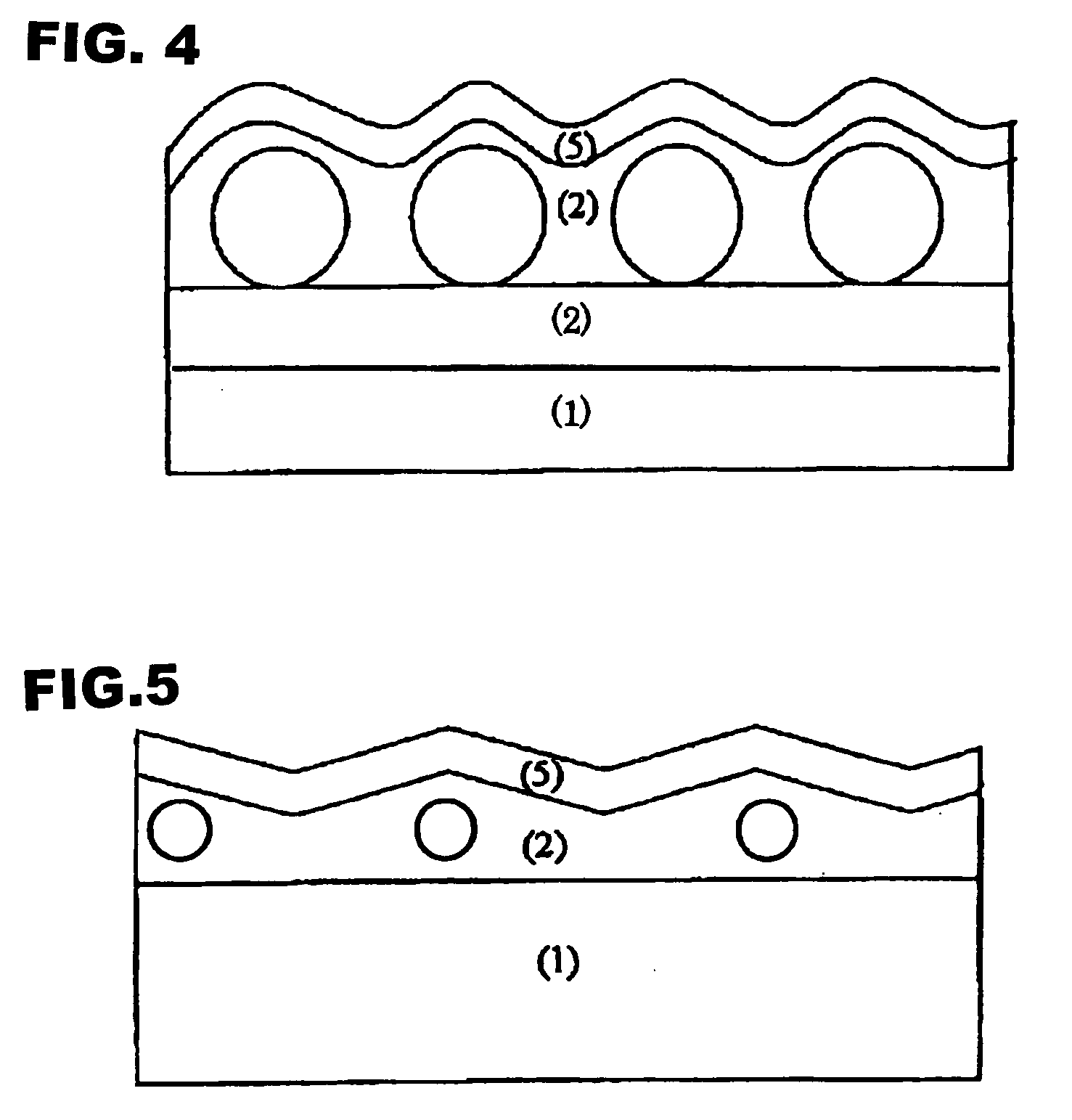

Image

  • Optical film, anti-reflection film, polarizing plate and image display device
  • Optical film, anti-reflection film, polarizing plate and image display device
  • Optical film, anti-reflection film, polarizing plate and image display device

Examples


examples

[0514]The invention will be described in more detail by reference to Examples which, however, do not limit the invention in any way.

[0515]Additionally, in Examples, “parts” are by mass.

Synthesis of Thickening Agent (V-1)

[0516]A solution of 1.32 g of sodium oleate and 0.18 g of sodium hydrogen carbonate in 332 g of distilled water was placed in a 1000-ml reactor equipped with a stirrer, a monomer-supplying tank, a thermometer, a cooling tube and a nitrogen gas-introducing tube, followed by heating to 65° C. in an atmosphere of nitrogen. Subsequently, 38 mg of potassium persulfate dissolved in 30 g of distilled water was added thereto, and the mixture was stirred for 30 minutes. Then, 132 g of ethyl methacrylate was dropwise added thereto over 5.5 hours and, after completion of the dropwise addition, the mixture was further heated for 6 hours under stirring. The mixture was then cooled to room temperature and, after filtering off insolubles, was dropwise added to 0.05 mol / dm3 of dilut...

examples 1-1 to 1-11

and Comparative Examples 1-1 to 1-5

(Preparation of a Coating Solution for Forming a Hard Coat Layer)

[0525]Components described in the following Table 1 were mixed and then filtered through a polypropylene-made filter of 30 μm in pore size to prepare coating solutions for forming a hard coat layer, HL-1 to HL-14.

[0526]Additionally, in Table 1, the amount of each component is shown in part by mass.

TABLE 1HL-1HL-2HL-3HL-4HL-5HL-6HL-7Thickening agent V-10.51.44.14.14.1STN0.51.4Polymethyl methacrylateSANPET-3030.629.727.127.127.130.629.7DPHA1.61.61.41.41.41.61.6Sol solution a-18.18.18.18.18.18.18.1Irgacure 1841.61.61.61.61.61.61.6Dispersion of 8-μm size cross-9.09.09.09.09.0linked polymethylmethacrylate particflesDispersion of 3.5-μm size9.0cross-linked polymethylmethacrylate particflesDispersion of 17-μm size9.0cross-linked polymethylmethacrylate particflesMethyl ethyl ketone15.715.715.715.715.715.715.7Methyl isobutyl ketone33.033.033.033.033.033.033.0HL-8HL-9HL-10HL-11HL-12HL-13HL-14Th...

examples 2-1 to 2-15

and Comparative Examples 2-1 to 2-5

(Preparation of Anti-Reflection Films C-1 to C-20 by Simultaneous Double-Layer Coating)

(1) Providing a Hard Coat Layer by Coating

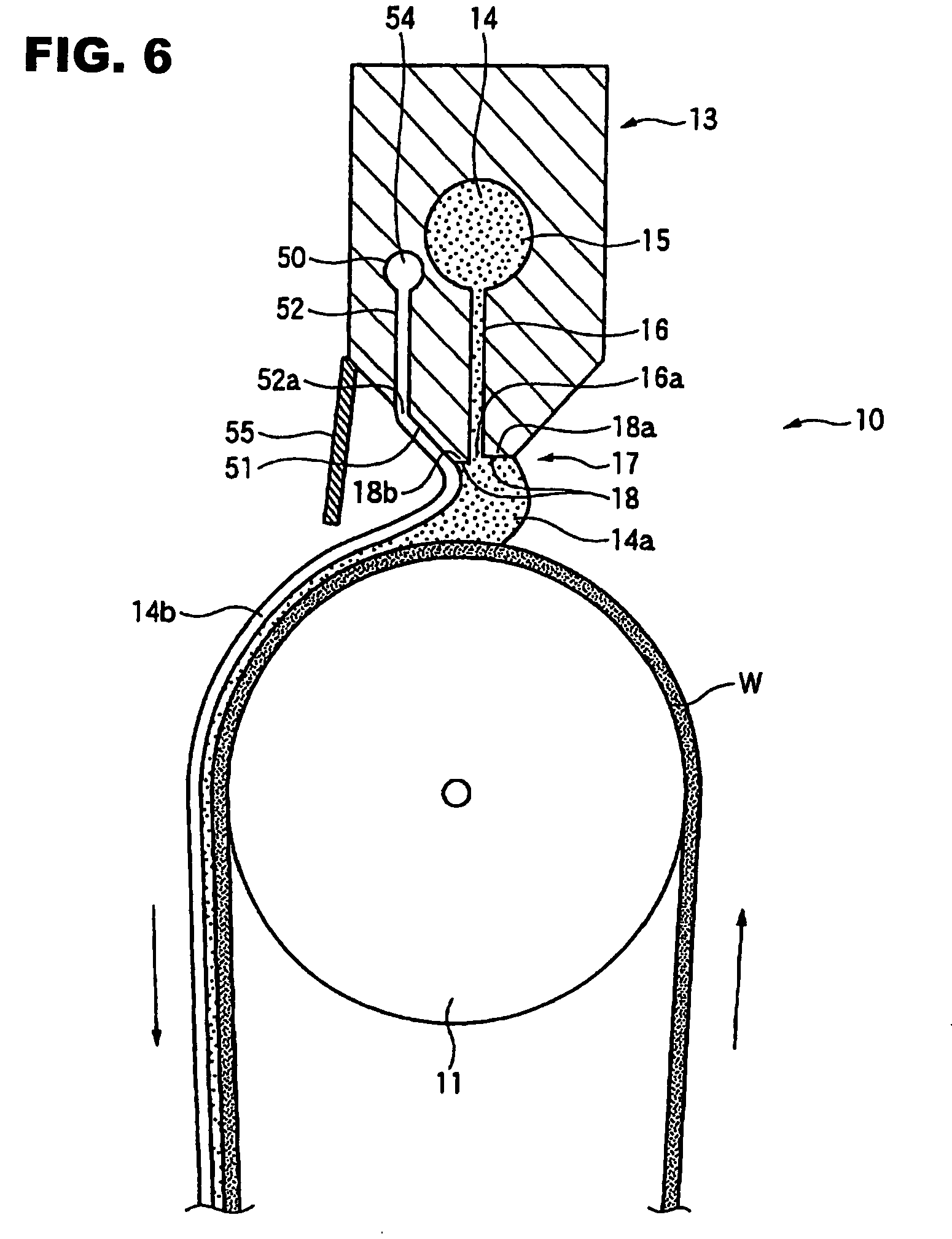
[0562]A 80-μm thick triacetyl cellulose film (FUJITAC TD80UF; manufactured by Fuji Photo Film Co., Ltd.; Re=2 nm; Rth=48 nm) was unwound, and each of coating solutions HL-1 to HL-14 for forming a hard coat layer and each of coating solutions LL-1 to LL-3 for forming a low refractive index layer were coated thereon according to a die coating method under the following conditions shown in Table 3 using a coater shown in FIG. 6 under the following fundamental conditions and, after drying at 30° C. for 15 seconds, then at 90° C. for 60 seconds, was irradiated with UV rays in an atmosphere of 0.1% in oxygen concentration under nitrogen purge in an irradiation amount of 300 mJ / cm2 using a 240 W / cm air-cooled metal halide lamp (manufactured by Eye Graphics Co., Ltd.) and, further, dried for 8 minutes at 100 C to cure the coated ...


PUM

PropertyMeasurementUnit
Lengthaaaaaaaaaa
Percent by massaaaaaaaaaa

Abstract

An optical film, which comprises: a transparent support; and an optical layer on or above the transparent support, wherein the optical layer contains a thickening agent which shows a viscosity of 10 mPa·sec or more when added to 2-butanone in a content of 3% by mass, and the optical layer has a thickness of 5 μm or more.

Description

BACKGROUND OF THE INVENTION[0001]1. Field of the Invention[0002]The present invention relates to an optical film, anti-reflection film, a polarizing plate and an image display device using them.[0003]2. Description of the Related Art[0004]In recent years, development of materials using various coating methods has advanced and, particularly, techniques of forming a thin layer of a level of from several μm to several ten nm are required in the field of optical films, printing and photo-lithography. The required coating accuracy has been increased with reduction in film thickness, increase in size of substrates and increase in coating speed. In particular, in the production of optical films, control of film thickness is an extremely important point that dominates optical performance, and there has been an increasing demand for a technique which can realize high-speed coating with maintaining accuracy at a high level.[0005]Of the optical films, an anti-reflection film is generally dispo...

Claims


Application Information

Patent Timeline
IPC IPC(8): B32B7/02
CPCG02B1/118G02B5/0226G02B5/0268Y10T428/24975G02B5/0294G02F1/133502G02B5/0278G02B1/11G02B5/20G02B5/30
Inventor SUZUKI, TAKATOASAKURA, TETSUYAWATANABE, JUN
Owner FUJIFILM CORP
Learn More