Crusher with joint filling function for traffic road and bridge construction

A traffic road bridge and crusher technology, applied in roads, roads, road repair and other directions, can solve the problems of poor use effect, poor crushing and mixing effect, etc., and achieve the effects of convenient construction and use, good crushing effect and high efficiency.

Active Publication Date: 2020-12-08
谢晓红
View PDF6 Cites 1 Cited by
  • Summary
  • Abstract
  • Description
  • Claims
  • Application Information

AI Technical Summary

Problems solved by technology

[0004] However, the above-mentioned device has poor crushing and mixing effect on materials, and the effect of selective humidification and mixing for standby use is not good, so it needs to be improved.

Method used


Image

  • Crusher with joint filling function for traffic road and bridge construction
  • Crusher with joint filling function for traffic road and bridge construction
  • Crusher with joint filling function for traffic road and bridge construction

Examples


Embodiment 1

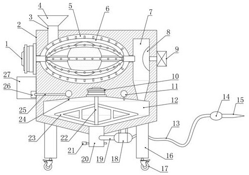
[0030] see figure 1 , in an embodiment of the present invention, a crusher for traffic road and bridge construction with a caulking function, comprising a body 2, a crushing cavity 5 is opened on the inner upper part of the body 2, the crushing cavity 5 is an ellipsoidal structure, and the crushing cavity 5 is installed with a crushing mechanism 6, and the crushing mechanism 6 is driven to rotate by the first motor 1 installed on the left side wall of the body 2, and the right side of the crushing chamber 5 is provided with a settling chamber 7, and the lower part of the settling chamber 7 is Conical, the crushing chamber 5 communicates with the settling chamber 7 through the crushing mechanism 6, the negative pressure fan 9 corresponding to the level of the crushing mechanism 6 is installed on the right side wall of the body 2, and the connecting port between the negative pressure fan 9 and the settling chamber 7 There is also a material blocking screen 8 protruding from the ...

Embodiment 2

[0036] see Figure 1-4 , the difference between this embodiment and embodiment 1 is:

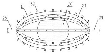
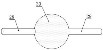
[0037] In this example, if figure 2 with 3 As shown, the crushing mechanism 6 includes a support shaft 28, a support pipe 29, a spherical filter screen 30, an arc crushing rod 31 and a crushing tooth 32. The support shaft 28 and the support pipe 29 are coaxially arranged, and the support shaft 28 and the support The tubes 29 are all rotatably connected with the body 2, and a spherical filter screen 30 is installed and fixed between the support shaft 28 and the support tube 29, and the inner wall of the spherical filter screen 30 is also provided with a convex edge (not shown) that allows the material to move to the support tube 29. out), and the support tube 29 communicates with the inner cavity of the spherical filter 30, the other end of the support tube 29 extends into the settling chamber 7, and the inner cavity of the spherical filter 30 communicates with the settling cavity 7 throug...


PUM


Abstract

The invention relates to traffic road and bridge construction equipment, in particular to a crusher with a joint filling function for traffic road and bridge construction. The crusher comprises a machine body, a crushing cavity is formed in the upper part of the inner side of the machine body, a crushing mechanism is mounted in the crushing cavity, and a settling cavity is formed in the right sideof the crushing cavity. A negative-pressure fan horizontally corresponding to the crushing mechanism and communicating with the settling cavity is mounted on the right side wall of the machine body,a mixing cavity is formed in the lower portion of the inner side of the crushing cavity, a rotating shaft is mounted in the middle of the mixing cavity, a plurality of mixing blades are further mounted on the rotating shaft in the circumferential direction, and a liquid spraying assembly is arranged at the top of the mixing cavity. The liquid spraying assembly is connected with a liquid storage tank arranged on the outer side wall of the machine body. The crusher is good in concrete crushing and mixing effect, can selectively humidify and uniformly mix concrete for later use, has the joint filling function with buffer protection, and is beneficial to popularization and application.

Description

technical field [0001] The invention relates to equipment for traffic road and bridge construction, in particular to a crusher for traffic road and bridge construction with the function of filling gaps. Background technique [0002] With the development of society, more and more old buildings are dismantled, leaving a lot of large particles, which can be used as aggregates of new buildings after being crushed. In the prior art, natural sand and gravel are directly used as aggregates of new buildings, and new aggregates and cement are mixed with water to obtain concrete slurry, which is solidified and formed into buildings. Although it is possible to use concrete slurry for joint filling in the prior art, the disadvantages of this technology are: due to the limited resources of natural sand and gravel, there will be less and less natural sand and gravel in the future, and the materials will become more and more expensive. In addition, large particle materials (building waste...

Claims


Application Information

Patent Timeline
Patent Type & Authority Applications(China)
IPC IPC(8): E01C23/09E01C19/05E01C19/10E01C19/46
CPCE01C19/05E01C19/1013E01C19/46E01C23/0966
Inventor 谢晓红
Owner 谢晓红
Why Eureka
Try Eureka