

Siphon-method flood-fighting and emergency rescue device
A siphon method and siphon technology, applied in water supply installations, water conservancy projects, embankments, etc., can solve problems such as reducing the use period of flood drainage systems and related rivers, delaying flood drainage time, personal and property losses, etc. Reuse, save manpower, material and financial resources, and form a simple effect
- Summary
- Abstract
- Description
- Claims
- Application Information
AI Technical Summary
Problems solved by technology
Method used
Image

Examples
Embodiment 1
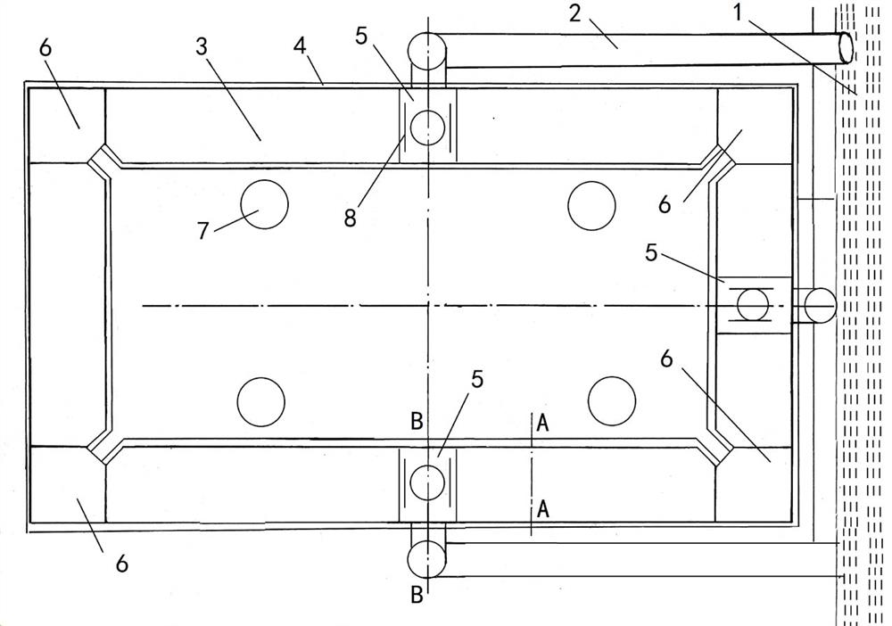
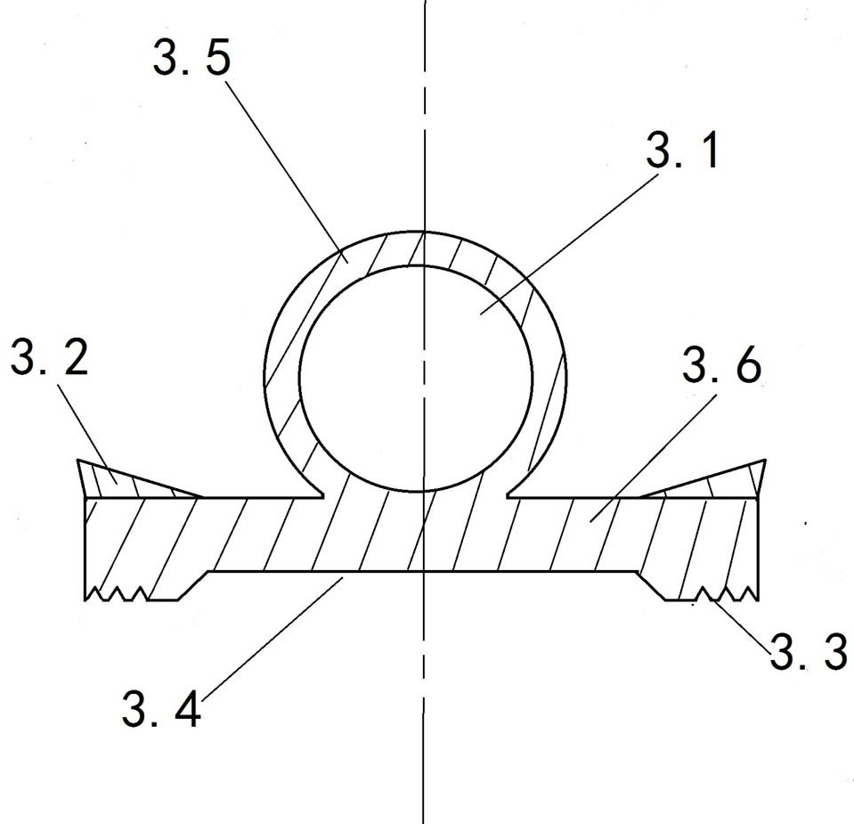
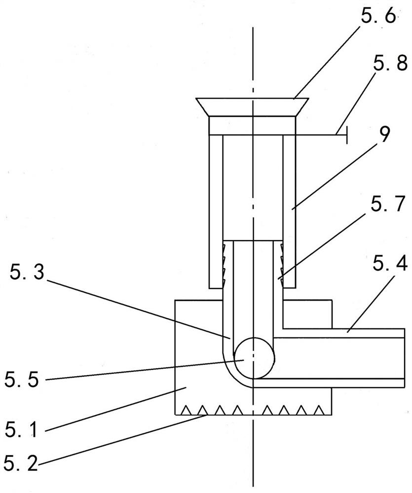
[0038] Embodiment 1, with reference to figure 1 , a kind of siphon method flood fighting rescue device mentioned in the present invention, comprises siphon water supply pipe 2, damming siphon water supply pipe 3, sand bag fixing area 4, siphon water supply station 5, siphon water supply station 6, outflow pump 7, The water delivery control valve 8 forms the first dammed lake a by enclosing the key flood-fighting areas, and installs a plurality of siphon water supply stations 6 around the key flood-fighting areas, and connects the dammed siphon water supply pipe 3 at the water outlet of the siphon water supply stations 6 , the outlet of the damming siphon water supply pipe 3 is connected to the siphon water delivery station 5, the water outlet of the siphon water delivery station 5 is connected to the siphon water delivery pipe 2, and extends to the flood discharge channel 1; the siphon water delivery station 5 is provided with a siphon The generation pipe 5.9 and the siphon sw...
Embodiment 2
[0052] Embodiment 2, a kind of siphon flood fighting rescue device mentioned in the present invention, differs from Embodiment 1 in that:
[0053] refer to Figure 8 , the end of the siphon water delivery pipe 2 located at the flood discharge channel 1 is connected to a water-absorbing faucet 9, the water-absorbing faucet 9 includes a base pipe 9.1, a speed-increasing blade 9.2, and a river water through hole 9.3, and the upper part of one end of the base pipe 9.1 is an elbow, It is used to connect to the end of the siphon water pipe 2, and the lower part of the other end of the base pipe is provided with multiple groups of penetrating river water through holes 9.3, and speed-increasing blades 9.2 are arranged on both sides of the river water through-holes 9.3, so that the river water flows through the speed-increasing The blade 9.2 will produce an acceleration effect to increase the speed of the river water passing through the river water through hole 9.3, and the siphon effe...
Embodiment 3
[0057] Embodiment 3, difference with embodiment 2 is:
[0058] refer to Figure 10 , the speed-increasing vane 9.2 of the present invention adopts a rectangular structure, and the two side walls of the speed-increasing vane 9.2 can be designed with a raised structure, which can increase the flow velocity of the river faster, thereby generating a greater siphon force and further improving the flow rate in the base pipe. of water velocity.
PUM
 Abstract
Description
Claims
Application Information