Deformation joint device for simple outer wall of steel structure building and construction method of deformation joint device

A construction method and technology of deformation joints, which are applied to buildings, building components, building structures, etc., can solve the problems of complicated connection structure and installation, high cost and construction period, and no connection structure, so as to achieve convenient installation and construction, and short construction period. , to ensure the overall effect

Pending Publication Date: 2020-12-08
广西建工第五建筑工程集团有限公司
View PDF0 Cites 2 Cited by
  • Summary
  • Abstract
  • Description
  • Claims
  • Application Information

AI Technical Summary

Problems solved by technology

[0003] 1. At present, most of the deformation joints used in construction projects are a finished deformation joint device, which is an industrial product. There is no unified national standard or industry standard for the deformation joint device. Most of them are enterprise standards prepared by manufacturers, and some local In this kind of atlas, the deformation joints are generally expressed as general structure and basic requirements, and further in-depth design is required by the design institute;
[0004] 2. The scope of use of the above-mentioned deformation joints is mostly limited to concrete structures or masonry structures, but for steel structures (steel columns on both sides of the expansion joint), there is no corresponding applica

Method used


Image

  • Deformation joint device for simple outer wall of steel structure building and construction method of deformation joint device
  • Deformation joint device for simple outer wall of steel structure building and construction method of deformation joint device
  • Deformation joint device for simple outer wall of steel structure building and construction method of deformation joint device

Examples


Embodiment 1

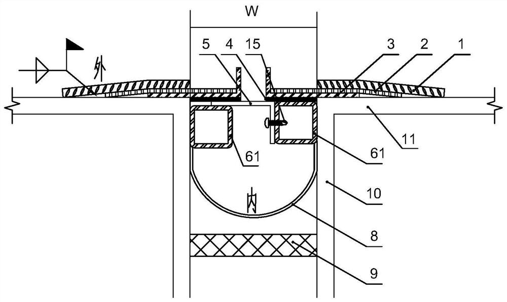
[0076] A deformation joint device for a simple exterior wall of a steel structure building. The deformation joint device is a device for covering the deformation joint of a simple exterior wall of a steel structure building. The two sides of the deformation joint of a simple exterior wall of a steel structure building are respectively the left steel column and the Right steel column; the deformation joint device includes a keel 6, an inner cover plate 5, an outer cover plate 3 and a steel wire mesh 2, the keel is a galvanized square tube 61, and the galvanized square tube is symmetrically installed on the left steel column and The inner side of the right steel column, that is, the galvanized square tube on the left is installed on the inner side of the left steel column, the galvanized square tube on the right is installed on the inner side of the right steel column, and the inner cover plate 5 is a metal plate with an "L" shape structure , including a covering surface 51 and a...

Embodiment 2

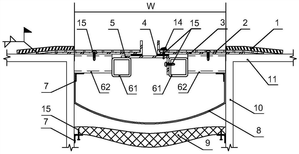
[0084] A deformation joint device for a simple exterior wall of a steel structure building. Its basic structure is the same as that of Embodiment 1. The left steel column and the right steel column are rectangular steel columns with the same structure, including a rectangular steel column web 10 and a rectangular steel column. Steel column wing plate 11;

[0085] The difference is:

[0086] The galvanized square pipe is connected to the web of the rectangular steel column through a transverse connecting pipe 62, that is, the left end of the left galvanized square pipe is connected to one end of the transverse connecting pipe 62, and the other end of the transverse connecting pipe is connected to the web of the rectangular steel column on the left. Plate connection, the right end of the right galvanized square tube is connected to one end of the transverse connecting pipe 62, and the other end of the transverse connecting pipe is connected to the right rectangular steel column ...

Embodiment 3

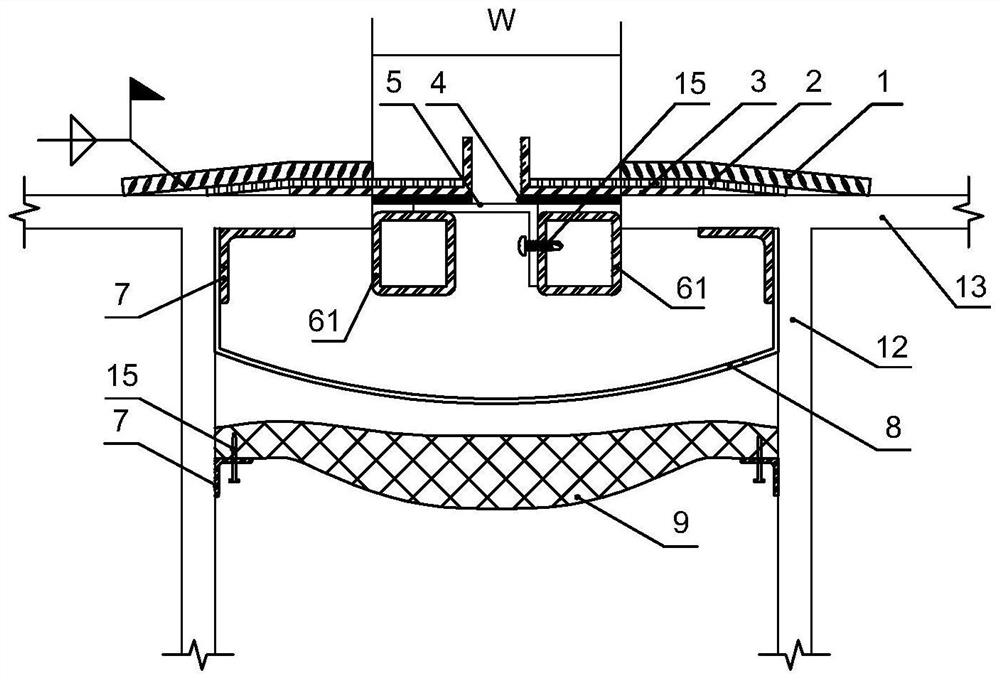
[0089] A deformation joint device for a simple exterior wall of a steel structure building, its basic structure is the same as that of Embodiment 1, the difference is:

[0090] The left steel column and the right steel column are H-shaped steel columns with the same structure, including the H-shaped steel column web 12 and the H-shaped steel column flange 13;

[0091] The galvanized square tube is installed symmetrically on the inner side of the flange of the left and right H-shaped steel column flanges, that is, the left galvanized square tube is directly connected with the flange of the left H-shaped steel column flange and installed on the H-shaped steel On the inner side of the flange of the column flange, the galvanized square tube on the right is directly connected with the flange of the H-shaped steel column flange on the right and installed on the inner side of the flange of the H-shaped steel column flange.

[0092] The inner side of the keel is successively installed...


PUM

PropertyMeasurementUnit
Diameteraaaaaaaaaa
Lengthaaaaaaaaaa
Thicknessaaaaaaaaaa

Abstract

The invention provides a deformation joint device for a simple outer wall of a steel structure building. The deformation joint device comprises galvanized square pipes symmetrically mounted on the inner sides of a left steel column and a right steel column, an inner cover plate, an outer cover plate and a steel wire mesh, wherein the inner cover plate, the outer cover plate and the steel wire meshcover a deformation joint; a waterproof rubber strip is mounted between the outer cover plate and the inner cover plate, and a rubber water stop belt and a heat preservation and insulation layer arearranged in the deformation joint device; the deformation joint device is complete and attractive in appearance and has the waterproof, fireproof, heat insulation and anti-cracking capacity; when a main structure is greatly deformed, the inner cover plate and the outer cover plate can freely move to adapt to structure deformation of the building under the adverse working conditions such as earthquakes and wind loads; and the deformation joint device is mounted in a layered mode from bottom to top, and mounting of each layer comprises the following steps that S1, the surfaces of the steel columns are cleaned and trimmed; S2, keels are mounted; S3, the inner cover plate is mounted; S4, the rubber water stop belt is mounted; S5, the heat preservation and insulation layer is mounted; S6, the outer cover plate is mounted; S7, the steel wire mesh is covered; and S9, quality inspection and acceptance are conducted. The site construction method is simple and convenient, the construction periodis short, the construction cost is low, and the engineering quality is easy to control.

Description

technical field [0001] The invention relates to a building structure device and a construction method, in particular to a deformation joint device for a simple outer wall of a steel structure building and an installation and construction method thereof. Background technique [0002] The deformation joint device refers to the device that covers the expansion joints of the external wall of the building. The deformation joint device must not only protect the integrity and beauty of the appearance of the joints of the building, but also adapt to the structural deformation of the building under adverse working conditions such as earthquakes and wind loads. When the architectural design requires it, the deformation joints have the ability of waterproof, fire prevention and heat insulation after the corresponding structure is configured. The problems existing in the deformation joints currently used in construction projects are: [0003] 1. At present, most of the deformation join...

Claims


Application Information

Patent Timeline
IPC IPC(8): E04B1/68E04B1/684E04B1/78E04B1/94
CPCE04B1/68E04B1/6803E04B1/6806E04B1/6812E04B1/78E04B1/948
Inventor 刘冶敏李书文陈立森王江杨小利董韶亮
Owner 广西建工第五建筑工程集团有限公司
Why Eureka
Try Eureka