Urban traffic rail nondestructive testing system and nondestructive testing method based on machine vision

A non-destructive testing and urban transportation technology, applied in the direction of optical testing flaws/defects, etc., can solve the problems of affecting the testing results, long distance, increased distance between the non-destructive testing instrument and the track, etc., to avoid potential safety hazards, facilitate close contact, avoid The effect of deviation

Inactive Publication Date: 2020-12-08
广州立信电子科技有限公司
View PDF0 Cites 0 Cited by
  • Summary
  • Abstract
  • Description
  • Claims
  • Application Information

AI Technical Summary

Problems solved by technology

[0006] The present invention can solve the problem that when the cart is pushed, the track of the cart often deviates from the predetermined track due to manual push, which causes the distance between the non-destructive testing instrument and the track to increase or decrease, thereby affecting the detection result. And because there is still a certain distance between the platform and the track, the distance between the non-destructive testing instrument on the moving trolley on the platform and the track may be relatively long, and it may be difficult to detect some small structural changes on the track in time. If it is not in place, it will easily lead to problems such as potential safety hazards in the later stage

Method used


Image

  • Urban traffic rail nondestructive testing system and nondestructive testing method based on machine vision
  • Urban traffic rail nondestructive testing system and nondestructive testing method based on machine vision
  • Urban traffic rail nondestructive testing system and nondestructive testing method based on machine vision

Examples


Embodiment Construction

[0037] Embodiments of the present invention will be described below with reference to the drawings. In the process, in order to ensure the clarity and convenience of illustration, we may exaggerate the width of the lines or the size of the constituent elements in the diagram.

[0038] In addition, the following terms are defined based on the functions in the present invention, and may be different according to the user's or operator's intention or practice. Therefore, these terms are defined based on the entire content of this specification.

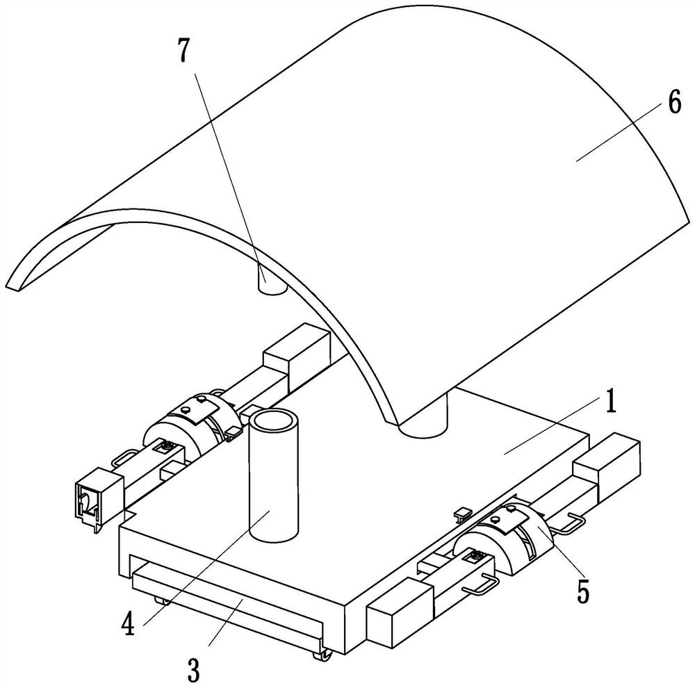
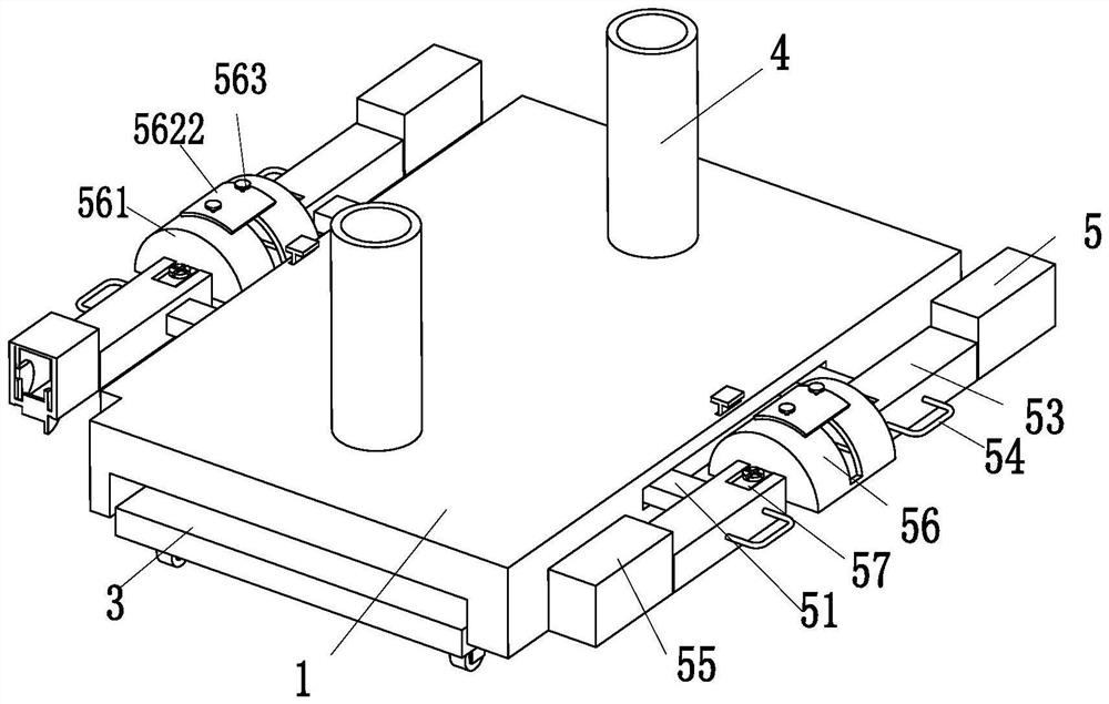
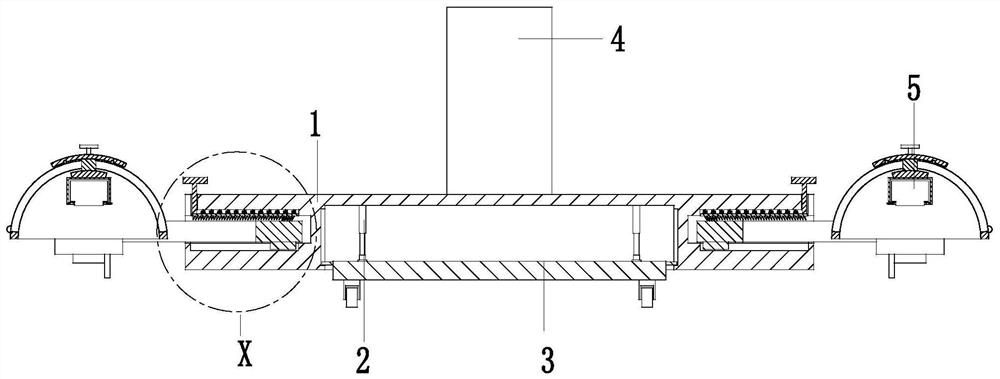
[0039] Such as Figure 1 to Figure 7 As shown, a non-destructive inspection system for urban traffic rails based on machine vision includes a base 1, a connecting cylinder 2, a mobile platform 3, a clamping cylinder 4, two monitoring units 5, a canopy 6 and an embedded column 7, the described The lower end of the base 1 is connected with the mobile platform 3 through the connecting cylinder 2, the upper end of the base 1 is symmetrical...


PUM


Abstract

The invention relates to an urban traffic rail nondestructive testing system and nondestructive testing method based on machine vision, the urban traffic rail nondestructive testing system comprises abase, a connecting cylinder, a mobile platform, clamping cylinders, two monitoring units, an awning and an embedded column, the lower end of the base is connected with the mobile platform through theconnecting cylinder, and the upper end of the base is symmetrically provided with the clamping cylinders; an embedded column is arranged above the clamping cylinder, and the upper end of the embeddedcolumn is installed on the shielding awning. According to the system, the problems that the distance between the nondestructive detector and the track is increased or decreased and the detection result is influenced due to the fact that the track of the cart often deviates from the preset track because the cart is mostly pushed manually when the cart is pushed, and a certain distance still existsbetween the platform and the track can be solved. The problem that the distance between a nondestructive testing instrument on a cart in a moving state on a platform and a rail can be far, some tinystructural changes on the rail can be difficult to find in time, and potential safety hazards exist in the later period easily due to the fact that inspection is not in place are solved.

Description

technical field [0001] The invention relates to the technical field of urban rail transit, in particular to a nondestructive detection system and nondestructive detection method for urban traffic rails based on machine vision. Background technique [0002] Non-destructive testing refers to the use of changes in thermal, sound, light, electricity, magnetic and other reactions caused by abnormal internal structures or defects of materials without damaging or affecting the performance of the tested object and the internal organization of the tested object. , by means of physical or chemical methods, with the help of modern technology and equipment, to inspect the structure, nature, state and type, nature, quantity, shape, position, size, distribution and changes of the internal and surface of the test piece In the daily maintenance of urban traffic, non-destructive testing is required, and the maintenance of the track also requires non-destructive testing. [0003] In the non-...

Claims


Application Information

Patent Timeline
Patent Type & Authority Applications(China)
IPC IPC(8): G01N21/88
CPCG01N21/88
Inventor 沈方园田仁江
Owner 广州立信电子科技有限公司
Why Eureka
Try Eureka