
Stamping device for guard plate of computer case

A stamping device and computer technology, applied in the field of stamping equipment, can solve problems such as product scrapping, increased production costs, and inability to clean up waste, achieving good cleaning effects and improving work efficiency

Active Publication Date: 2020-12-11
JIANGHAI POLYTECHNIC COLLEGE
View PDF21 Cites 0 Cited by
  • Summary
  • Abstract
  • Description
  • Claims
  • Application Information

AI Technical Summary

Problems solved by technology

[0003]1. Computer chassis shield stamping equipment will produce a lot of debris during the stamping process, and many stamping equipment cannot remove the debris on the workbench in a timely and efficient manner. It greatly affects the stamping effect of the product, and even leads to the scrapping of the product, thus affecting the production efficiency of the enterprise;
[0004]2. Existing stamping devices for computer case shields cannot clean up the remaining waste after stamping, and often need to use other auxiliary devices to clean up, which increases the production cost At the same time, it also affects the overall production efficiency;
[0005]3. Due to the thinness of the protective plate of the computer case, many stamping equipment cannot control the clamping force of the plate well, too large or too small will affect The stamping effect of the product

Method used


Image

  • Stamping device for guard plate of computer case
  • Stamping device for guard plate of computer case
  • Stamping device for guard plate of computer case

Examples


Embodiment Construction

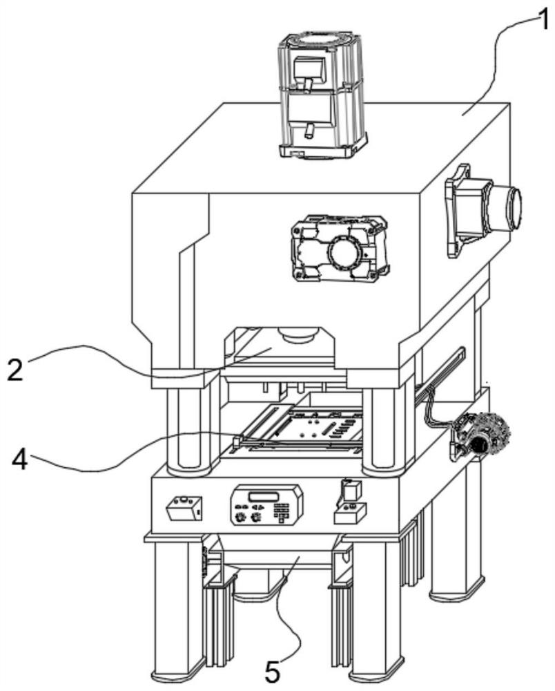
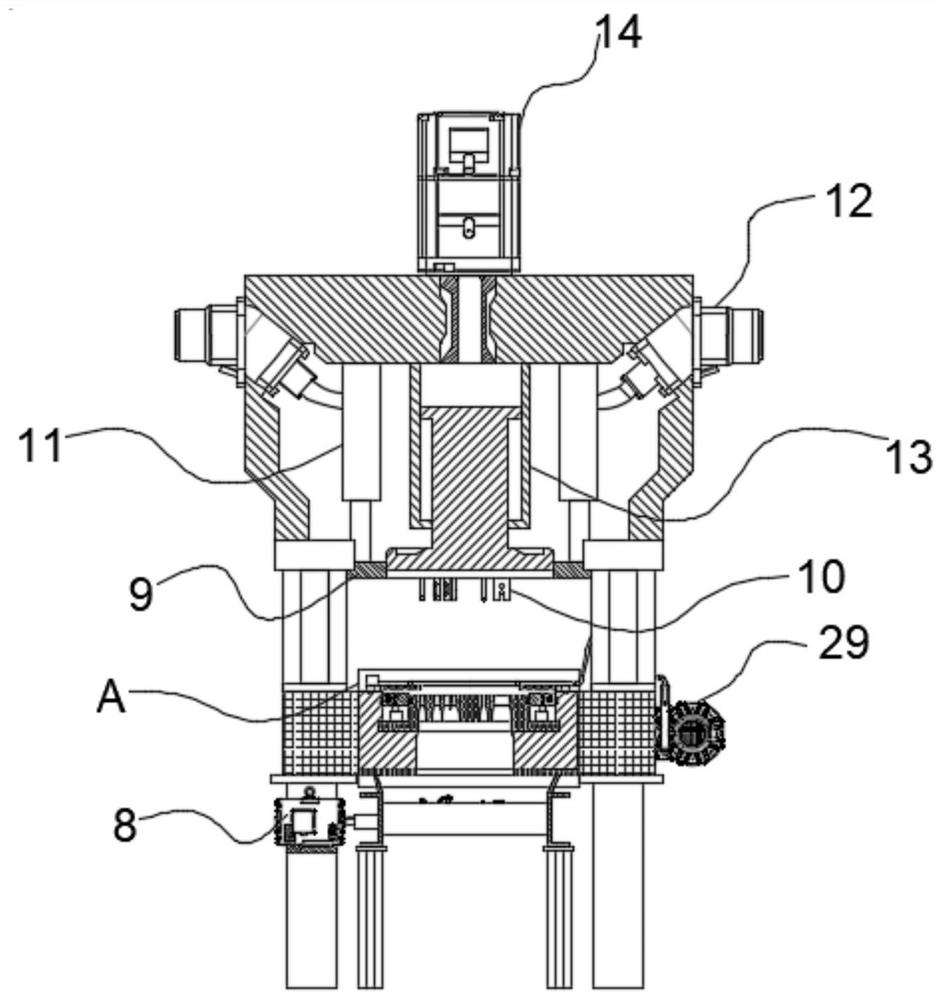
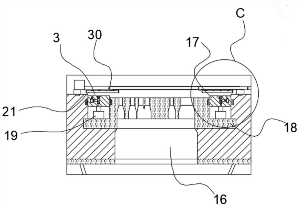
[0039] see figure 1 , 3 , in an embodiment of the present invention, a stamping device for a computer case shield, which includes: a casing 1, a stamping assembly 2, a fixing assembly 3, a dust removal assembly 4, and a conveyor belt 5, and the stamping assembly 2 is arranged above the casing 1 , for punching and stamping the guard plate, the fixing assembly 3 is used to fix the guard plate on the workbench 7, and the dust removal assembly 4 is slidably connected to the workbench 7;

[0040] The conveyor belt 5 is arranged at the bottom of the workbench 7, the left side of the conveyor belt 5 is connected with a drive motor 8, the two sides and the rear side of the conveyor belt 5 are respectively equipped with baffle plates, and the top of the baffle plate is connected to the bottom of the workbench 7. Fitting, so that the debris falling from the punching can all fall on the conveyor belt 5 and be transferred to the waste bin 6 , and the conveyor belt 5 is used to transport ...


PUM


Abstract

The invention discloses a stamping device for a guard plate of a computer case. The stamping device for the guard plate of the computer case comprises a machine shell, a stamping assembly, a fixing assembly, a dust removal assembly and a conveying belt, wherein the stamping assembly is used for punching and stamping forming of an outer plate; the fixing assembly is arranged below the stamping assembly; the dust removal assembly is slidably connected to a workbench; the conveying belt is arranged at the bottom of the workbench; a first driving motor is connected to the left side of the conveying belt; baffles are arranged on the two sides and the rear side of the conveying belt respectively; the top ends of the baffles are attached to the bottom of the workbench; and the conveying belt is used for conveying waste generated by stamping to a waste box.

Description

technical field [0001] The invention belongs to the technical field of punching equipment, in particular to a punching device for a protective plate of a computer case. Background technique [0002] With the continuous development of science and technology, the replacement speed of computers is getting faster and faster, the market demand is also increasing, and the production efficiency requirements of computer manufacturers are also getting higher and higher. For computer case shields, It is necessary to use stamping equipment to stamp the plate to obtain the required formed computer case shield. However, according to investigations, the current stamping devices for computer case shields often have the following problems: [0003] 1. The stamping equipment for computer case shields will produce a lot of debris during the stamping process. Many stamping equipment cannot clean up the debris on the workbench in a timely and efficient manner, which greatly affects the stamping...

Claims


Application Information

Patent Timeline
IPC IPC(8): B21D35/00B21D43/00B08B1/00B08B5/02B21D45/00B21D45/02B21D43/20
CPCB21D35/001B21D43/003B08B5/02B21D45/003B21D45/02B21D43/20B08B1/30
Inventor 陈天文
Owner JIANGHAI POLYTECHNIC COLLEGE
Learn More