Multi-angle feeding and discharging manipulator applied to heat treatment furnace and numerically-controlled milling machine
A technology for heat treatment furnaces and CNC milling machines, which is applied to furnaces, furnace components, lighting and heating equipment, etc., can solve the problems of inconvenient transportation and reclaiming, difficult pushing and receiving operations, and poor device use effect, and saves money. Labor cost, the effect of improving practicability
- Summary
- Abstract
- Description
- Claims
- Application Information
AI Technical Summary
Problems solved by technology
Method used
Image

Examples
Embodiment Construction
[0022] Combine below Figure 1-9 The present invention is described in detail, wherein, for the convenience of description, the orientations mentioned below are defined as follows: figure 1 The up, down, left, right, front and back directions of the projection relationship itself are the same.
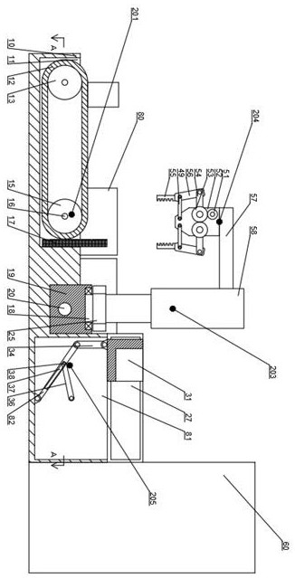
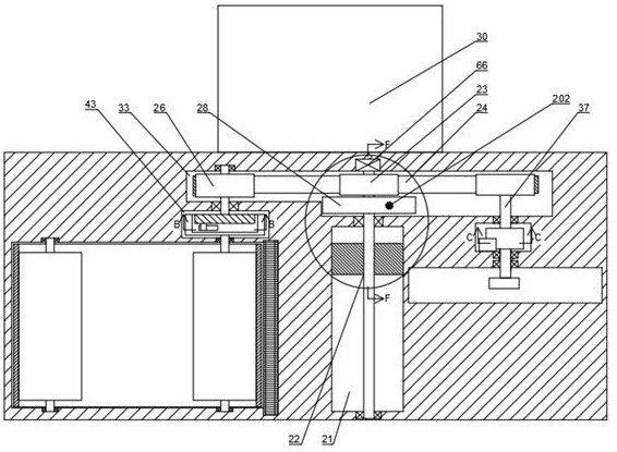
[0023] combined with Figure 1-9The manipulator for multi-angle loading and unloading, which is applied to heat treatment furnaces and CNC milling machines, includes a body 10 and a transfer chamber 11 that opens upward in the left end wall of the body 10, and the transfer chamber 11 There is a transmission device 201 that can only move parts to the right through the rotation of the transmission belt 12. A recovery box 80 is placed on the rear side of the transmission chamber 11, and a heat treatment furnace 30 is placed on the right rear side of the recovery box 80. The rear end wall of the fuselage 10 is provided with a first transmission cavity 33, and the front end wall of the fi...
PUM
 Abstract
Description
Claims
Application Information