
A steel-plastic combined concrete prefabricated component mold and demoulding method thereof

A prefabricated component and concrete technology, applied in the field of concrete molds, can solve the problems of increasing the cost of the mold, affecting the quality of the components, increasing the demoulding force, etc., and achieving the effects of easy release, low labor cost, and ensuring the quality of components

Active Publication Date: 2022-06-24
HUNAN WUXIN MACHINERY
View PDF15 Cites 0 Cited by
  • Summary
  • Abstract
  • Description
  • Claims
  • Application Information

AI Technical Summary

Problems solved by technology

Increase the demoulding force to force the component to come out, there is a risk of damage to the component, and the mold needs to be strengthened, which will further increase the cost of the mold; directly opening holes in the mold will cause the mold to leak, and the strength of the leaking part of the component will decrease , affecting the component quality
In addition, when the existing mold is demolded, the mold needs to be turned over first, and then the components are poured out of the mold cavity. This method is easy to cause damage to the components, and the corresponding mechanism is very complicated and the cost is high

Method used


Image

  • A steel-plastic combined concrete prefabricated component mold and demoulding method thereof
  • A steel-plastic combined concrete prefabricated component mold and demoulding method thereof
  • A steel-plastic combined concrete prefabricated component mold and demoulding method thereof

Examples


Embodiment 1

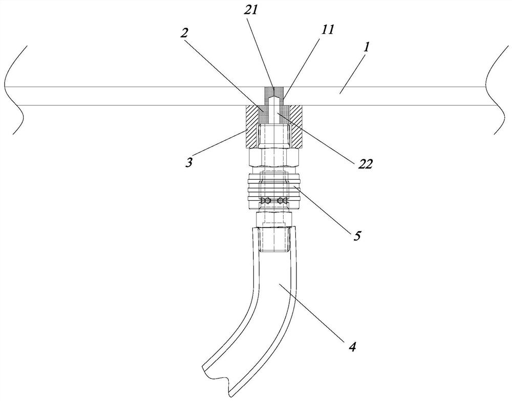
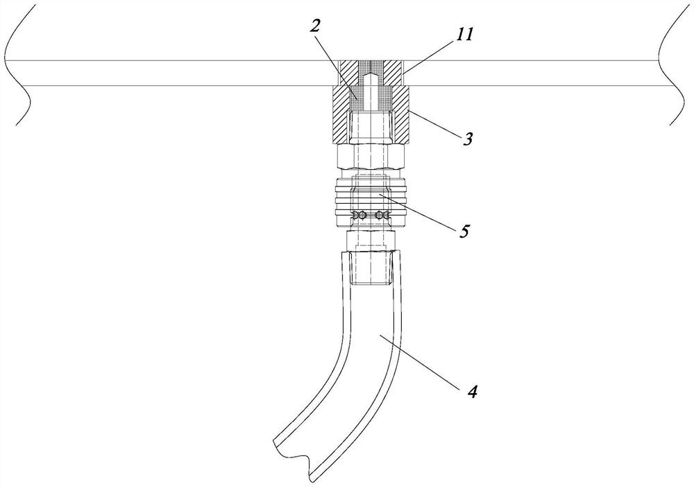
[0033] figure 1 , figure 2 and Figure 4 to Figure 7 An embodiment of the steel-plastic combined concrete prefabricated component mold of the present invention is shown. The steel-plastic combined concrete prefabricated component mold of this embodiment includes a plurality of plastic molds 1 and a steel frame 6 for supporting each plastic mold 1. , the plastic mold 1 includes a mold cavity 12 and a first connecting portion 13 arranged on the side of the mold cavity 12, a second connecting portion 61 is provided on the steel frame 6, and the first connecting portion 13 is fixedly connected with the second connecting portion 61 , each mold cavity 12 is provided with a mounting hole 11 and is equipped with an intake plug 2, one end of the intake plug 2 is provided with a first air intake portion 21 that can be opened and closed, and the other end is provided with a first air intake portion 21 The second air inlet portion 22 communicated with each other, the end of the air inl...

Embodiment 2

[0043] image 3 Another embodiment of the steel-plastic combined concrete prefabricated component mold of the present invention is shown. The steel-plastic combined concrete prefabricated component mold of this embodiment is basically the same in structure as the first embodiment, with the difference that: in this embodiment , the installation hole 11 is a threaded hole, and the air plug sleeve 3 is provided with an external thread and is arranged in the installation hole 11 through the external thread. Compared with the first embodiment, the threaded connection structure can facilitate the disassembly of the gas plug sleeve 3 .

Embodiment 3

[0045] like Figure 8 As shown, the demolding method based on the above-mentioned mold of the present embodiment comprises the following steps:

[0046] S1, the external gas or liquid enters the second air inlet portion 22 of the air inlet plug 2 and the first air inlet portion 21 is opened, and then the external gas or liquid enters the mold cavity 12 through the first air inlet portion 21;

[0047] S2. The vacuum suction cup 91 or the component clamp 92 on the component hanger 9 fixes the component 8, and then the component hanger 9 rises to lift the component 8 out of the mold cavity 12;

[0048] S3. The component hanger 9 transfers the component 8 to the stacking position, and the vacuum suction cup 91 or the component clamp 92 releases the component 8 to complete the stacking.

[0049] In this demolding method, the air inlet plug 2 is first ventilated (or liquid such as water is introduced) to increase the pressure in the mold cavity 12, so that after the component 8 is ...


PUM


Abstract

A concrete prefabricated member mold combining steel and plastic, including a plurality of plastic molds and a steel frame, the plastic mold includes a mold cavity and a first connecting part, the steel frame is provided with a second connecting part, and the first connecting part is connected to the second Each mold cavity is provided with a mounting hole and equipped with an air intake plug. One end of the air intake plug is provided with a first air intake section that can be opened and closed, and the other end is provided with a second air intake section that communicates with the first air intake section. Two air inlets, one end of the air inlet plug provided with the first air inlet is set in the installation hole and is in a squeezed state to close the first air inlet. The demoulding method includes the steps: S1, external air or liquid enters the second air intake part of the air intake plug and opens the first air intake part, and the external air or liquid enters the mold cavity through the first air intake part; S2, The vacuum cups or component clamps on the component hanger hold the component, and then the component hanger rises to lift the component out of the mold cavity. The invention has the advantages of simple structure, low cost, convenient demoulding and guaranteed component quality.

Description

technical field [0001] The invention relates to a concrete mould, in particular to a steel-plastic combined concrete prefabricated component mould and a demoulding method thereof. Background technique [0002] Precast concrete components need to be produced using molds. Common molds include steel molds and plastic molds. Compared with plastic molds, steel molds have better durability and stronger resistance to deformation. One mold can integrate multiple mold cavities, so it can produce multiple molds at a time. The components have high efficiency and large output. The overall cost of mold and labor is lower than that of plastic molds during long-term mass production. However, the molding process of steel molds is complicated and difficult to manufacture. Or the component is damaged, and the molding effect of the component is not as good as that of the plastic mold. The single cost of plastic molds is lower than that of steel molds. It is made by injection molding process. ...

Claims


Application Information

Patent Timeline
Patent Type & Authority Patents(China)
IPC IPC(8): B65D51/16B28B7/34B28B7/26B28B7/12B28B7/00B28B13/06
CPCB28B7/348B28B7/26B28B7/12B28B7/0002B28B7/0014B28B13/065B28B13/062
Inventor 李佑福吴忠盛郑怀臣毛成宝张维颂
Owner HUNAN WUXIN MACHINERY
Learn More