Novel anti-adhesion rubber forming machine
A rubber molding machine and anti-adhesion technology, applied in the field of industrial machinery, can solve the problems of rubber deformation and affect the processing speed of rubber, and achieve the effect of convenient collection and guarantee of integrity
- Summary
- Abstract
- Description
- Claims
- Application Information
AI Technical Summary
Problems solved by technology
Method used
Image
Examples
Embodiment 1
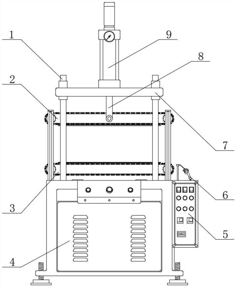
[0027] Such as figure 1 As shown, a new type of anti-adhesion rubber molding machine includes a cabinet 4 and a control box 5, the right end of the cabinet 4 is welded and fixedly connected to the control box 5, the upper end of the control box 5 is connected with a shedding device 6, and the bottom The upper end surface of the extrusion device 3 is connected with a support rod 1, and the middle of the support rod 1 is connected with a lower extrusion device 3 at the position of the upper end surface of the cabinet 4, and the top of the lower extrusion device 3 is at the middle position of the support rod 1 Connected with an upper extruding device 2, the top of the upper extruding device 2 is connected with a fixed plate 7 at the outer surface of the support rod 1, the upper end of the fixed plate 7 is connected with a hydraulic cylinder 9, and the lower end of the hydraulic cylinder 9 is on the upper surface. The front end surface and the rear end surface of the extrusion dev...
Embodiment 2
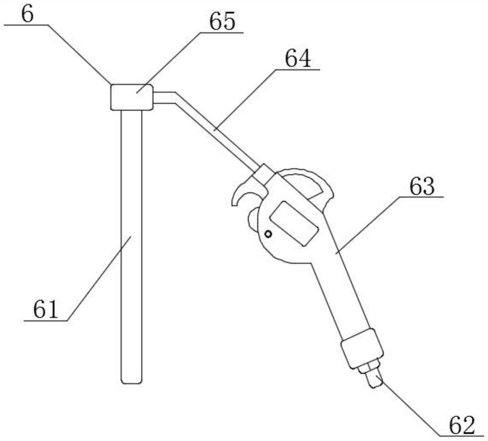
[0030] Such as Figure 1-3As shown, a new type of anti-adhesion rubber molding machine includes a cabinet 4 and a control box 5. The right end of the cabinet 4 is welded and fixedly connected to the control box 5, and the upper end of the control box 5 is connected to a shedding device 6. The upper end surface of the extrusion device 3 is connected with a support rod 1, and the middle of the support rod 1 is connected with a lower extrusion device 3 at the position of the upper end surface of the cabinet 4, and the upper part of the lower extrusion device 3 is at the middle position of the support rod 1 Connected with an upper extruding device 2, the top of the upper extruding device 2 is connected with a fixed plate 7 at the outer surface of the support rod 1, the upper end of the fixed plate 7 is connected with a hydraulic cylinder 9, and the lower end of the hydraulic cylinder 9 is on the upper surface. The front end surface and the rear end surface of the extrusion device ...
Embodiment 3
[0033] Such as Figure 1-4 As shown, a new type of anti-adhesion rubber molding machine includes a cabinet 4 and a control box 5. The right end of the cabinet 4 is welded and fixedly connected to the control box 5, and the upper end of the control box 5 is connected to a shedding device 6. The upper end surface of the extrusion device 3 is connected with a support rod 1, and the middle of the support rod 1 is connected with a lower extrusion device 3 at the position of the upper end surface of the cabinet 4, and the upper part of the lower extrusion device 3 is at the middle position of the support rod 1 Connected with an upper extruding device 2, the top of the upper extruding device 2 is connected with a fixed plate 7 at the outer surface of the support rod 1, the upper end of the fixed plate 7 is connected with a hydraulic cylinder 9, and the lower end of the hydraulic cylinder 9 is on the upper surface. The front end surface and the rear end surface of the extrusion device...
PUM
 Abstract
Description
Claims
Application Information
 - R&D
- Intellectual Property
- Life Sciences
- Materials
- Tech Scout
- Unparalleled Data Quality
- Higher Quality Content
- 60% Fewer Hallucinations
Browse by: Latest US Patents, China's latest patents, Technical Efficacy Thesaurus, Application Domain, Technology Topic, Popular Technical Reports.
© 2025 PatSnap. All rights reserved.Legal|Privacy policy|Modern Slavery Act Transparency Statement|Sitemap|About US| Contact US: help@patsnap.com


