Locking mechanism and battery fixing device
A locking mechanism and locking position technology, applied in the direction of electric power devices, power devices, battery pack components, etc., can solve problems such as locking failure, easy deformation of small balls, and unsmooth locking, so as to reduce stress concentration, Simple and efficient installation structure
- Summary
- Abstract
- Description
- Claims
- Application Information
AI Technical Summary
Problems solved by technology
Method used
Image

Examples
Embodiment 1
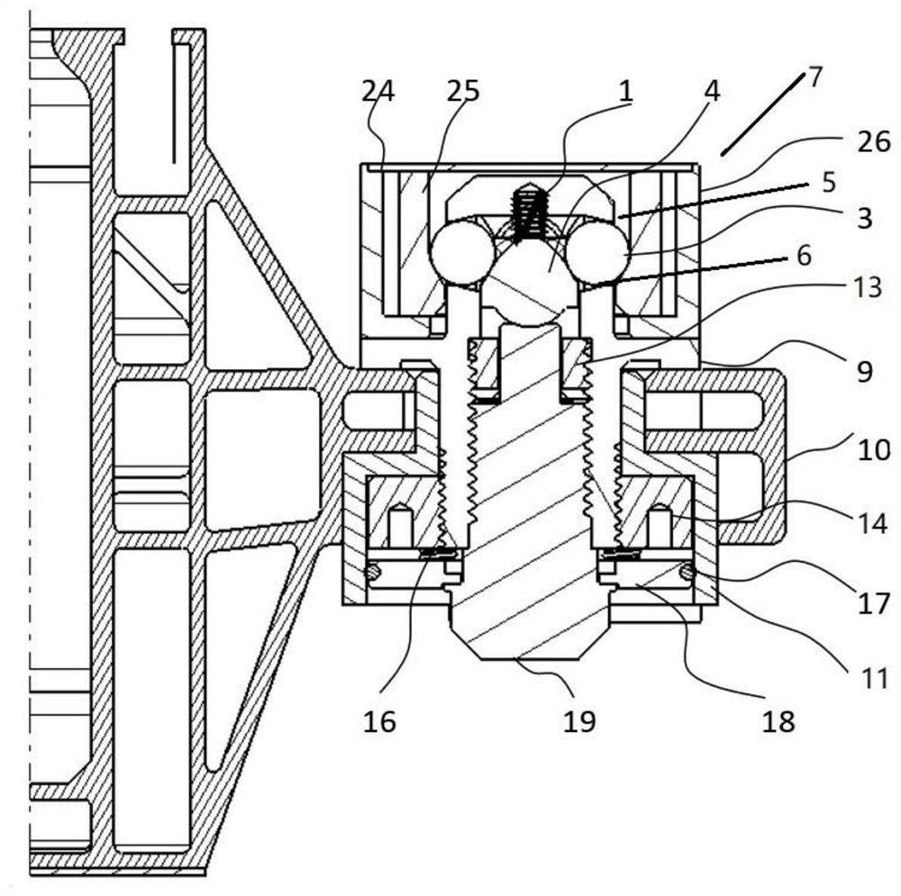
[0042] Such as Figure 1-5 As shown, a locking mechanism includes a locking connector 7, a locking housing 5, a jacking device and a locking ball 3; The protruding locking hole 6, the aperture of the locking hole 6 is smaller than the outer diameter of the locking ball, to prevent the locking ball from falling off.
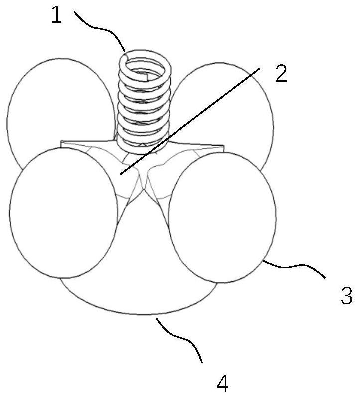
[0043] The jacking device includes a jacking block 4 and a jacking rod 19, and the jacking block 4 is used to push the locking ball 3 out of the locking hole.
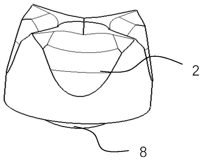
[0044] The ejection block 4 has an ejection groove 2 that cooperates with the locking ball 3, and the upper end of the ejection block 4 is provided with an ejection block return spring 1, and the two ends of the ejection block return spring 1 are connected to the ejection block 4 and the locking housing 5 respectively. touch. There are four ejection grooves 2 and locking balls 3 in this embodiment, and the ejection grooves 2 are uniformly arranged on the ejection blocks 4 .
[0045] The jacking rod 19 i...
Embodiment 2
[0060] The difference from Embodiment 1 is that the jacking device includes a jacking block 4 and a jacking rod 19, and the jacking block is used to push the locking ball out of the locking hole. The jacking rod is integrally formed with the ejector block. The ejector block has an ejection groove that matches the locking ball. The upper end of the ejector block is provided with a reset spring of the ejector block. Both ends of the ejector block reset spring are respectively connected with the ejector block and the locking The shells are in contact.
Embodiment 3
[0062] The difference from Embodiment 1 is that the ejector block 4 has an ejector groove 2 that cooperates with the locking ball 3, and the upper end of the ejector block 4 is provided with an ejector block elastic reset member 1, which is specifically an ejector block reset spring, The two ends of the ejector block return spring are in contact with the ejector block 4 and the locking housing 5 respectively. There are 2 or 3 ejection grooves 2 and locking balls 3 in this embodiment, and the ejection grooves 2 are uniformly arranged on the ejection blocks 4 .
PUM
 Abstract
Description
Claims
Application Information
 - R&D
- Intellectual Property
- Life Sciences
- Materials
- Tech Scout
- Unparalleled Data Quality
- Higher Quality Content
- 60% Fewer Hallucinations
Browse by: Latest US Patents, China's latest patents, Technical Efficacy Thesaurus, Application Domain, Technology Topic, Popular Technical Reports.
© 2025 PatSnap. All rights reserved.Legal|Privacy policy|Modern Slavery Act Transparency Statement|Sitemap|About US| Contact US: help@patsnap.com