
construction material transport vehicle

A technology of building materials and transport vehicles, which is applied in the field of construction, can solve problems such as dislocation and jamming, and achieve the effect of evenly dividing nodes to buffer back force

Active Publication Date: 2021-12-03
JINHUA WINNER MECHANICAL&ELECTRICAL CO LTD ZHEJIANG
View PDF2 Cites 0 Cited by
  • Summary
  • Abstract
  • Description
  • Claims
  • Application Information

AI Technical Summary

Problems solved by technology

[0006] In order to solve the above-mentioned technology, when the steel bars are assembled in the transport vehicle, since the steel bars are cylindrical, the vibration generated during the transportation will make the steel bars staggered and stuck together, and loosen in many directions, which is easy to cause subsequent removal. misplaced stuck problem

Method used


Image

  • construction material transport vehicle
  • construction material transport vehicle
  • construction material transport vehicle

Examples


Embodiment 1

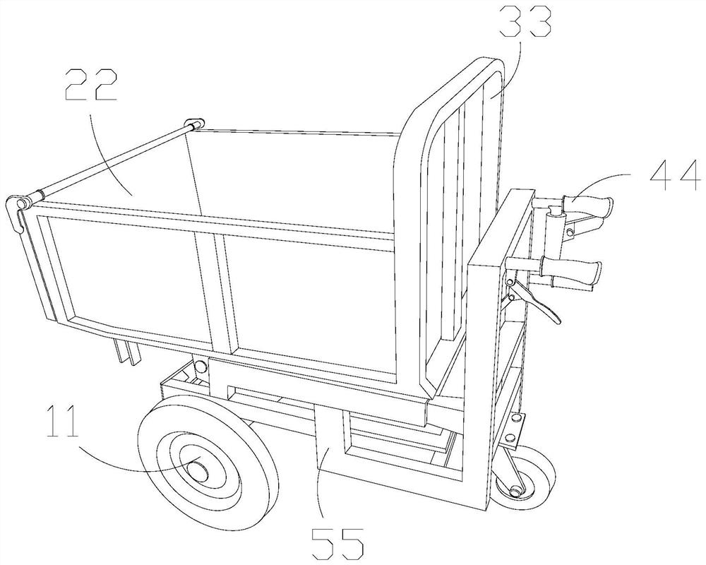
[0032] as attached figure 1 To attach Image 6 Shown:

[0033] The present invention provides a construction material transportation vehicle, the structure of which includes wheels 11, a storage grid 22, a fence 33, a grip frame 44, and a bottom bracket 55, the upper surface of the bottom bracket 55 is welded to the grip frame 44, and the The wheels 11 pass through the inside of the bottom bracket 55 , and the fence 33 is connected with the storage compartment 22 .

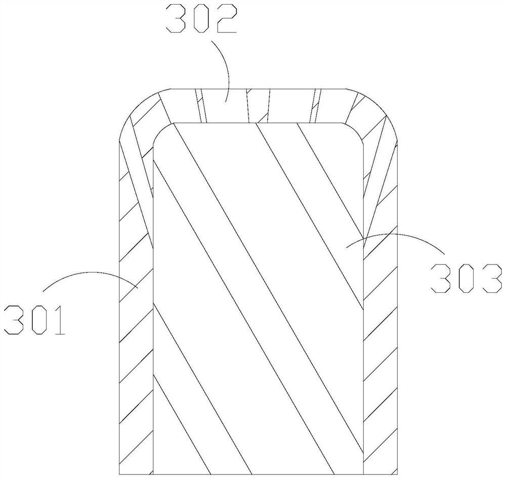
[0034] The fence 33 includes a main rod 301 , a pocket edge 302 , and a main board 303 , the main bar 301 and the main board 303 are an integrated structure, and the pocket edge 302 is connected with the main rod 301 .

[0035] Wherein, the pocket edge 302 includes a pocket layer 001, a main wrapping layer 002, and a peripheral block 003. The pocket layer 001 is attached to the outer surface of the main wrapping layer 002, and the left and right ends of the main wrapping layer 002 are in contact with the perimet...

Embodiment 2

[0042] as attached Figure 7 To attach Figure 9 Shown:

[0043] Wherein, the telescoping joint e02 includes an extended surface layer x11, a hard core x12, a pressure arc x13, and a space opening x14. The hard core x12 is embedded inside the extended surface layer x11, and the outer surface of the extended surface layer x11 is pasted The arc x13, the space opening x14 and the extended surface layer x11 are an integrated structure, the hard core x12 is a quadrilateral structure, there are two pressing arcs x13, the hard core x12 guides the movable guide on the outside, the When the pressing arc x13 is squeezed on both sides, it acts as a reaction force, and the space opening x14 gives the outer layer a certain space for movement.

[0044]Wherein, the pressing arc x13 includes an adhesive layer w10 and an overlapping angle w11, the overlapping angle w11 is connected with the adhesive layer w10, the overlapping angle w11 is made of rubber material and has a certain pulling eff...


PUM


Abstract

The invention discloses a building material transportation vehicle, the structure of which comprises wheels, a storage grid, a railing, a grip frame, and a bottom bracket. The upper surface of the bottom bracket is welded to the grip frame. The board is connected with the placement grid, so that the steel bar is leaned against the edge of the pocket, so that the pocket layer mainly wraps around the steel bar, and applies force to the main wrapping layer at the rear end, which limits the overall installation range. When the steel bar is placed in the original square position, it will form an arc on the pocket surface to fix the steel bar. The inner hard core will guide the actual direction of the extension layer. After one end of the extended surface layer is stressed, the overlapping angle at the middle end will act as a counter force through its own stretching force, assisting the expansion and contraction of the connecting parts. When the connecting parts are stressed, the range of motion is limited and the pulling effect is achieved. Function, the internal nodes will mainly bear the external pressure, which can assist the overall force to play the role of evenly distributed node buffer force.

Description

technical field [0001] The invention belongs to the construction field, and more specifically, relates to a construction material transportation vehicle. Background technique [0002] There are many scattered materials in the construction site, and most of them are transported and collected by hand trucks. The scattered materials need to be placed in the storage compartment, and then pushed and transported to the required location by manpower. [0003] Based on the inventor's discovery above, the existing building material transport vehicles mainly have the following deficiencies, such as: [0004] When the steel bars are assembled in the transport vehicle, because the steel bars are cylindrical, the vibration generated during the transportation will cause the steel bars to be interlaced and stuck together, and loosen in many directions, which is more likely to cause dislocation and jamming when they are removed later. [0005] Therefore need to propose a kind of constructi...

Claims


Application Information

Patent Timeline
Patent Type & Authority Patents(China)
IPC IPC(8): B62B3/04B62B3/10B62B5/00F16F15/08
CPCB62B3/005B62B3/04B62B3/104B62B5/0006B62B2202/02B62B2203/60F16F15/08
Inventor 刘国平
Owner JINHUA WINNER MECHANICAL&ELECTRICAL CO LTD ZHEJIANG
Learn More