Protective guard device for construction

A technology of guardrails and magnetic devices, applied in construction, building structure, processing of building materials, etc., can solve the problems of unallowable processing, low reliability, and inability to achieve convenient storage and transportation, a wide range of applications, cost saving effect

Inactive Publication Date: 2020-12-11
TAIYUAN HEAVY IND
View PDF5 Cites 1 Cited by
  • Summary
  • Abstract
  • Description
  • Claims
  • Application Information

AI Technical Summary

Problems solved by technology

However, these protective devices have some disadvantages
[0004] For example, scaffolding is mostly used in a large number of building constructions, while large machinery and large buildings have high and scattered border work areas, and the scaffolding scheme is less economical.
Another example is that temporary railings are not easy to fix. If they are fixed by binding, the method varies from person to person and the strength cannot be guaranteed; if they are fixed by welding, it will have an adverse effect on the mechanical properties or surface coating of the steel structure body; if they are fixed by bolts, they must be fixed Mounting holes are reserved on steel structures, while some steel structures cannot or do not allow processing of mounting holes
As another example, if the safety belt is suspended from a fall, it is necessary to find a suitable suspension point, and it can also affect the operator's flexibility and comfort
[0005] Therefore, in the process of large-scale mechanical installation or steel structure building construction, there are problems of inconvenient use and low reliability of fall prevention equipment.

Method used


Image

  • Protective guard device for construction
  • Protective guard device for construction
  • Protective guard device for construction

Examples


Embodiment Construction

[0035] In order to make the purpose, technical solution and advantages of the present invention clearer, the technical solution of the present invention will be clearly and completely described below in conjunction with specific embodiments of the present invention and corresponding drawings. Apparently, the described embodiments are only some of the embodiments of the present invention, but not all of them. Based on the embodiments of the present invention, all other embodiments obtained by persons of ordinary skill in the art without making creative efforts fall within the protection scope of the present invention.

[0036] The technical solutions provided according to the embodiments of the present invention will be described in detail below with reference to the accompanying drawings.

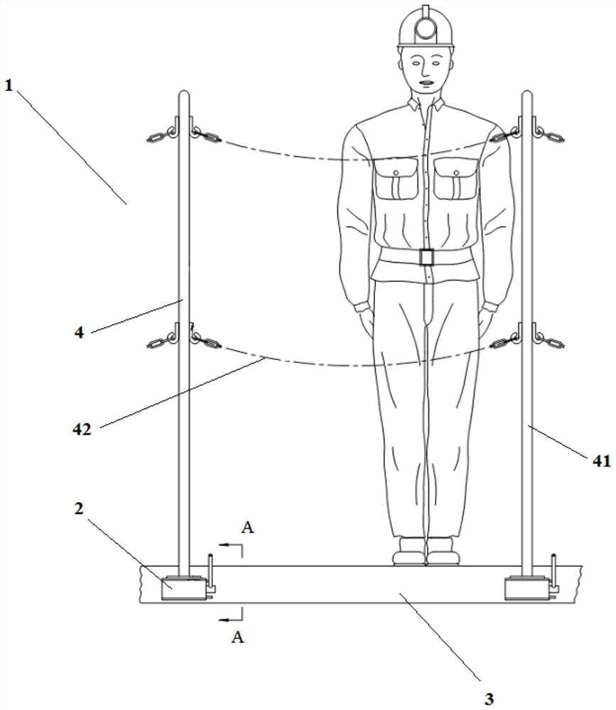
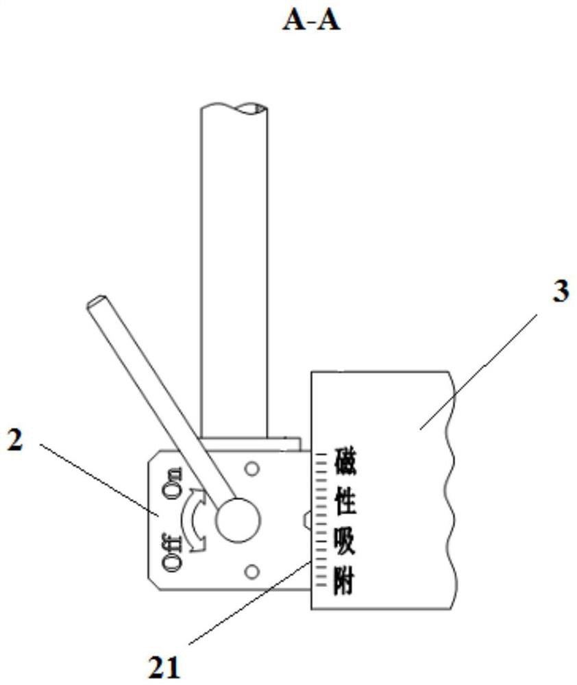
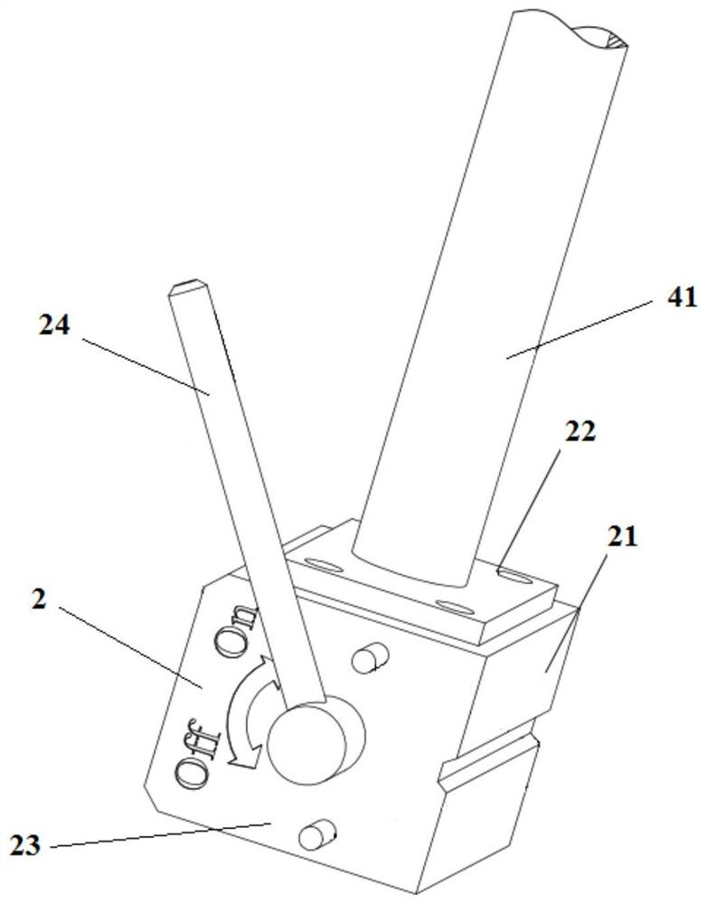
[0037] see Figures 1 to 4 , shows a construction guardrail device 1 according to an embodiment of the present invention, which is used to cooperate with a steel platform 3 supporting work...


PUM


Abstract

The invention discloses a protective guard device for construction. The protective guard device is used for being used in cooperation with a steel platform for supporting a worker, and comprises a plurality of permanent magnetic bases and a protective guard assembly; the permanent magnetic bases are respectively used for providing variable magnetic field intensity, and the multiple permanent magnetic bases respectively adsorb or separate the steel platform based on the magnitude of the magnetic field intensity provided by each permanent magnetic base; and the protective guard assembly comprises a plurality of vertical columns which are mounted on the permanent magnetic bases in dismounting and mounting modes correspondingly, and protection components connected between the vertical columns.During work, the protective guard device can be firmly adsorbed to the surface of the steel platform through the permanent magnetic bases made of high-performance permanent magnetic materials; and magnetism to the steel platform can be greatly weakened or eliminated during dismounting so that the protective guard device can be firmly adsorbed when working and can be easily and quickly dismountedand mounted when not working, and the protective guard device can be repeatedly used, can be suitable for various mounting environments, is wide in application range and economical in cost.

Description

technical field [0001] The invention relates to the technical field of safety protection equipment for construction, in particular to a protective fence device for construction. Background technique [0002] Generally speaking, in the process of large-scale mechanical installation or steel structure building construction, construction personnel often need to temporarily operate on some unprotected high-altitude platforms, that is, edge operations. In order to prevent falling, protective measures must be installed. [0003] Common protective measures may include providing protective devices such as scaffolding, temporary railings, and fall suspension safety belts. However, each of these guards has some drawbacks. [0004] For example, scaffolding is mostly used for mass construction, while the border work areas of large machinery and large buildings are high and scattered, and the scheme of scaffolding is less economical. Another example is that temporary railings are not ...

Claims


Application Information

Patent Timeline
Patent Type & Authority Applications(China)
IPC IPC(8): E04G21/32
CPCE04G21/3233
Inventor 张珏陈晓斌刘丽芳孙刚王勇澎
Owner TAIYUAN HEAVY IND
Why Eureka
Try Eureka