
Ignition resistor capable of enhancing firepower and manufacturing method thereof

A technology of ignition resistance and production method, which is applied to weapon accessories, offensive equipment, blasting tubes, etc., can solve the problems of insufficient contact surface, insufficient ignition ability of the resistance alloy layer, and failure to detonate, so as to avoid ignition failure, reliably detonate detonators, reduce The effect of rejection rate

Active Publication Date: 2021-08-17
深圳市开步电子有限公司
View PDF0 Cites 1 Cited by
  • Summary
  • Abstract
  • Description
  • Claims
  • Application Information

AI Technical Summary

Problems solved by technology

[0004] The resistance alloy layer on the chip alloy foil igniter is relatively narrow, which will lead to insufficient contact surface. If faced with insensitive agents, the narrow resistance alloy layer has insufficient ignition ability, which will easily lead to detonation failure.

Method used


Image

  • Ignition resistor capable of enhancing firepower and manufacturing method thereof
  • Ignition resistor capable of enhancing firepower and manufacturing method thereof
  • Ignition resistor capable of enhancing firepower and manufacturing method thereof

Examples


no. 1 approach

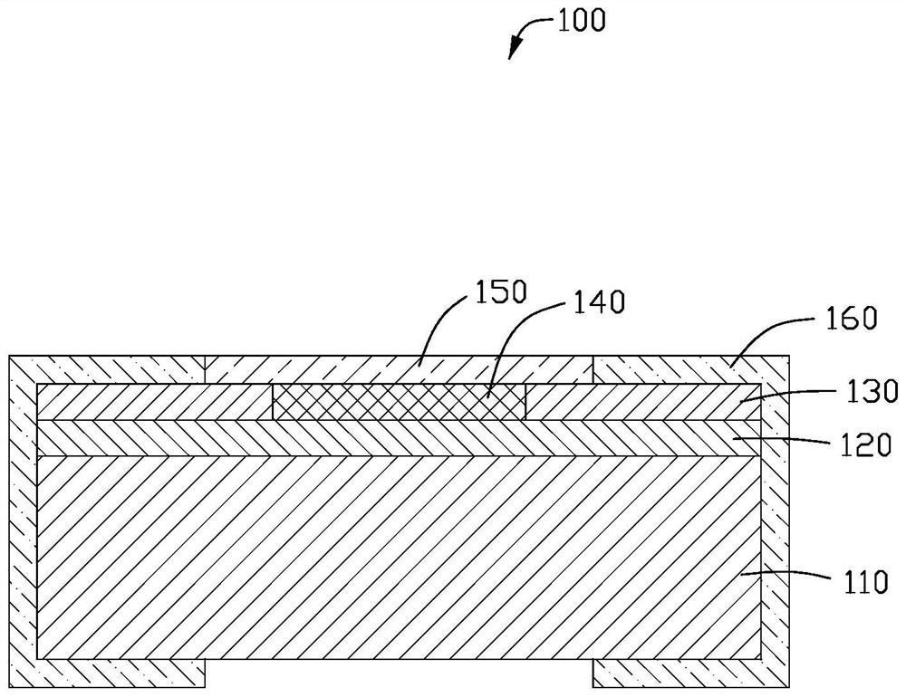
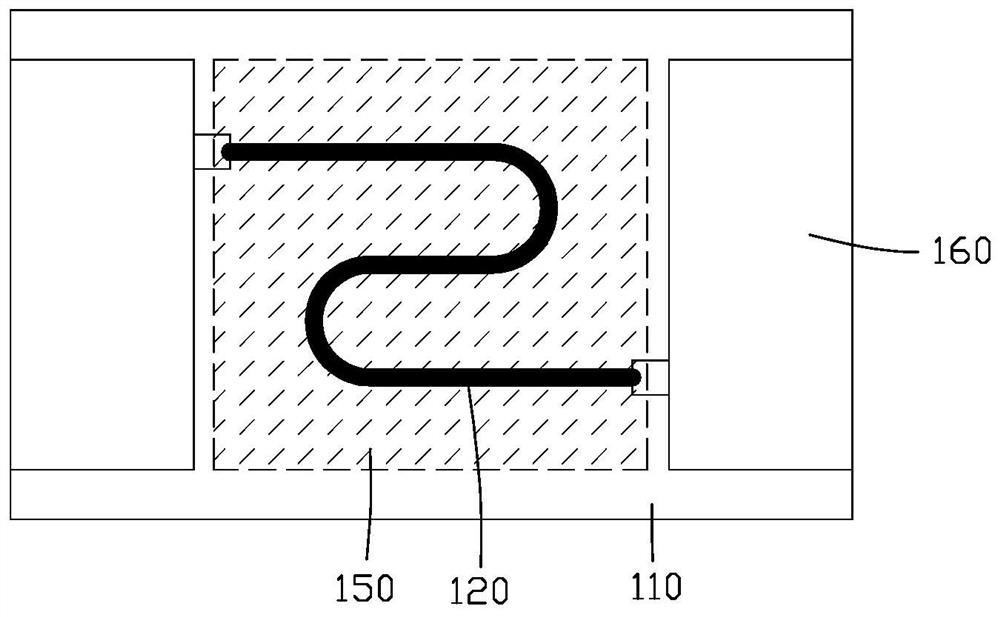
[0024] Such as figure 1 As shown, this embodiment provides an ignition resistor 100 that can enhance firepower. The resistor 100 includes a substrate 110, a resistance layer 120, a connection layer 130, an insulating layer 140, a metal combustion-supporting layer 150, and an electrode layer 160. The resistance layer 120 is located above the substrate 110, the metal combustion-supporting layer 150 is located above the resistance layer 120 and separated by the insulating layer 140, and the connecting layer 130 is located on the insulating layer 140. on both sides of the resistance layer 120, the electrode layer 160 is located on both sides of the metal combustion-supporting layer 150 and above the connection layer 130, the electrode layer 160 is connected from the connection layer 130 The upper surface extends toward the side of the substrate 110 and the back of the substrate 110, and the connection layer 130 connects the resistance layer 120 to the side electrodes and then to t...

no. 2 approach

[0038] The technical solution of the first implementation manner may be correspondingly applicable to this implementation manner, which will not be repeated here.

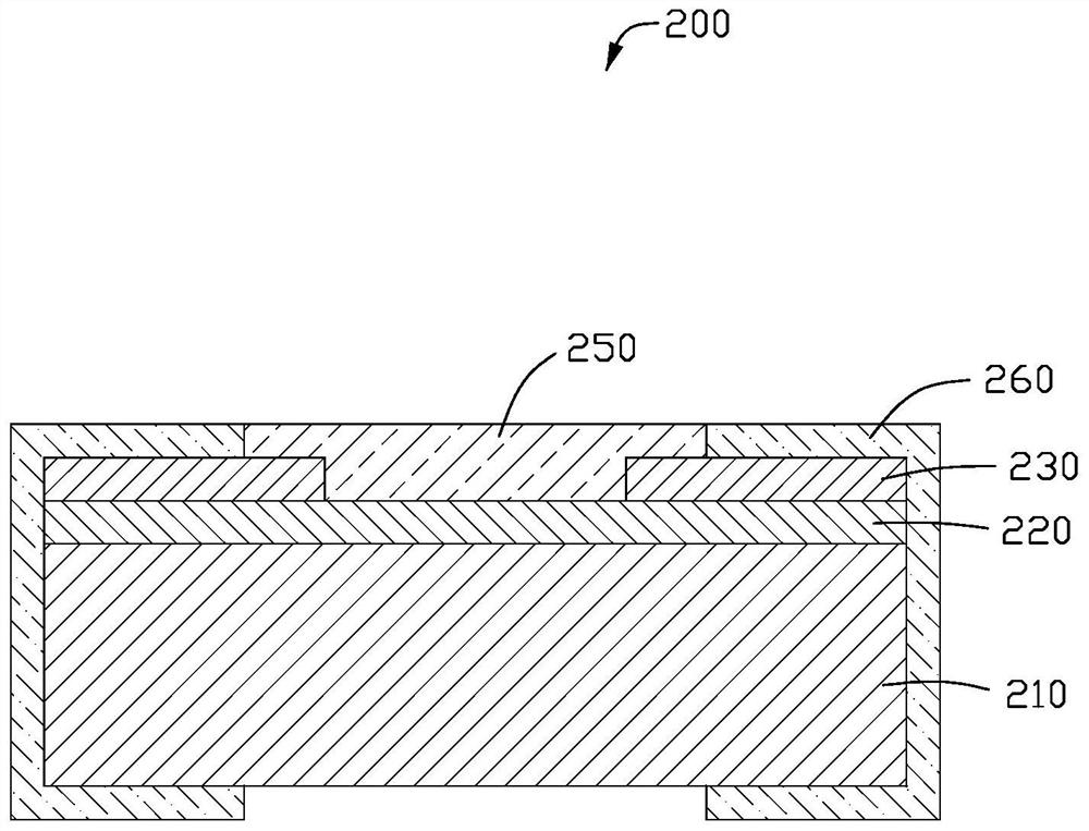
[0039] Such as image 3 As shown, this embodiment provides an ignition resistor 200 that can enhance firepower. The resistor 200 includes a substrate 210, a resistance layer 220, a connection layer 230, a metal combustion-supporting layer 250, and an electrode layer 260. The resistance layer 220 Located above the substrate 210, the metal combustion-supporting layer 250 is in direct contact with the resistance layer 220, the connection layer 230 is located on both sides of the metal combustion-supporting layer 250 and above the resistance layer 220, the The electrode layer 260 is located on both sides of the metal combustion-supporting layer 250 and above the connection layer 230 , and the electrode layer 260 extends from the upper surface of the connection layer 230 to the side of the substrate 210 and the Extendi...


PUM


Abstract

The invention provides an ignition resistor capable of enhancing firepower, the resistor includes a substrate, a resistance layer and a metal combustion-supporting layer, the resistance layer is located above the substrate, the resistance layer is connected to electrodes, and the metal combustion-supporting layer Located above the resistance layer and directly in contact with the resistance layer, the metal combustion-supporting layer is a non-conductive combustion-supporting material, and generates heat through the resistance layer to ignite the metal combustion-supporting layer. The invention enhances the ignition ability, reduces the rejection rate and avoids misfiring.

Description

technical field [0001] The invention relates to the technical field of electronic blasting, in particular to an ignition resistor capable of enhancing firepower and a manufacturing method. Background technique [0002] Unless specifically indicated otherwise, what is described in this section is not prior art to the present application and is not admitted to be prior art by inclusion in this section. [0003] The bridge wire igniter is the ignition method that has been commonly used by people. The radial stretching effect of the bridge wire can easily lead to deformation of the bridge wire, resulting in a change in the resistance of the bridge wire, which affects the ignition performance of the igniter, and may cause the bridge wire to break and cause the igniter to misfire. Therefore, people have developed a sheet-type alloy foil igniter. This igniter generally processes the alloy onto the substrate through a specific process, and forms a narrow alloy layer as an ignition ...

Claims


Application Information

Patent Timeline
Patent Type & Authority Patents(China)
IPC IPC(8): F42B3/12
CPCF42B3/12
Inventor 杨宝平
Owner 深圳市开步电子有限公司
Learn More