
Air slowly-releasing rod and sleep fresh air machine

A fresh air blower and slow-release technology, which is applied in space heating and ventilation, air conditioning systems, ventilation systems, etc., can solve problems such as not suitable for night use and single function of the fresh air system, and achieve complete functions, wide application areas, and resistance to fog haze effect

Inactive Publication Date: 2017-06-27
宋欣宇
View PDF11 Cites 1 Cited by
  • Summary
  • Abstract
  • Description
  • Claims
  • Application Information

AI Technical Summary

Problems solved by technology

[0004] The purpose of the present invention is to solve the problem that the existing fresh air system has a single function and is not suitable for use at night, in order to satisfy people’s beautiful luxury of being able to breathe fresh air from the outdoor nature while sleeping, and to provide an air slow-release stick and A sleep freshener that includes the slow-release air stick

Method used


Image

  • Air slowly-releasing rod and sleep fresh air machine
  • Air slowly-releasing rod and sleep fresh air machine
  • Air slowly-releasing rod and sleep fresh air machine

Examples


specific Embodiment approach 1

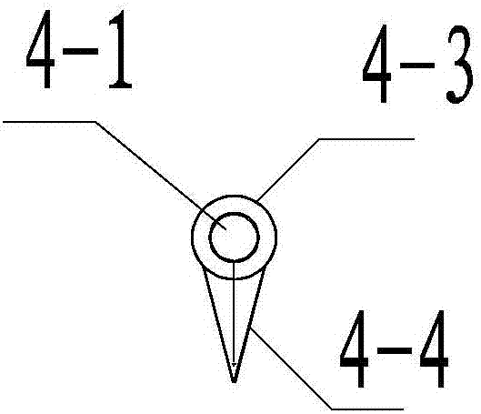
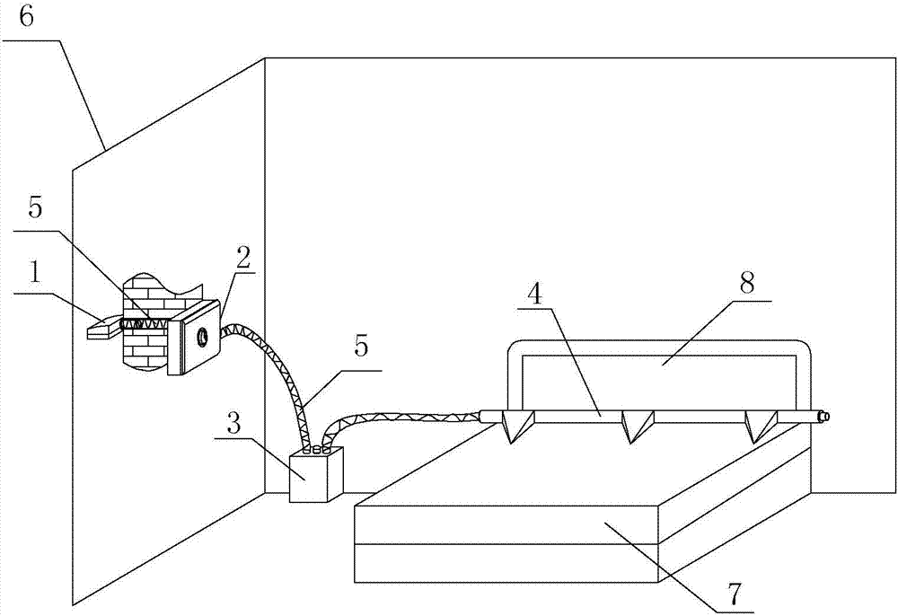
[0027] Specific implementation mode one: combine figure 1 and figure 2 Describe this embodiment. The air slow-release stick described in this embodiment includes a support part 4-1 and a slow-release cloth 4-2. The inside of the support part 4-1 is a flow channel for fresh air, and the slow-release cloth 4-2 wraps Outside the support part 4-1, and fresh air can seep from the inside of the support part 4-1 to the outside of the slow-release cloth 4-2.

[0028] Such as figure 1 and figure 2 As shown, the support part 4-1 can choose a tubular structure, one end of which is used to introduce fresh air, and a fresh air passage is provided on the side wall of the support part 4-1, so that the fresh air inside the support part 4-1 can flow out of the support through this passage. part 4-1, and then slowly oozes through the slow release cloth 4-2. One end of the support part 4-1 is connected to the main unit 2 of the fresh air system, and the other end can be in a closed state, ...

specific Embodiment approach 2

[0032] Specific implementation mode two: combination figure 1 This embodiment is described. This embodiment is a further limitation of the air slow-release stick described in Embodiment 4. In this embodiment, the support part 4-1 is realized by a spring.

[0033] Such as figure 1 As shown, the spring can not only play the role of supporting the slow-release cloth 4-2, but also make fresh air ooze out from the slow-release cloth 4-2 smoothly.

specific Embodiment approach 3

[0034] Specific implementation mode three: combination figure 1 and figure 2 Describe this embodiment. This embodiment is a further limitation of the air slow-release sticks described in Embodiments 4 and 5. In this embodiment, the support part 4-1 is also provided with a protruding structure 4-4. The fresh air inside the support part 4-1 can seep out through the protruding structure 4-4 and the slow-release cloth 4-2 wrapped outside the protruding structure 4-4.

[0035] Such as figure 1 and figure 2 As shown, the number of protruding structures 4-4 can be two or more, preferably two or three. figure 1 The shown air slow-release stick contains three raised structures 4-4, and the air slow-release stick is installed on the head of the bed. A mass of air forms around the head.


PUM


Abstract

The invention provides an air slowly-releasing rod and a sleep fresh air machine, relates to fresh air systems and aims to solve the problems that an existing fresh air system is singular in function and not suitable for being used at night. The air slowly-releasing rod comprises a supporting portion and slowly-releasing cloth; and the supporting portion is internally provided with a fresh air flowing channel, the slowly-releasing cloth wraps the supporting portion, and the fresh air can seep to the outer side of the slowly-releasing cloth from the interior of the supporting portion. The sleep fresh air machine comprises a draught fan, a main engine, a humidification tank and the air slowly-releasing rod; and the draught fan is arranged outside a room, the main engine and the humidification tank are arranged in the room, the air slowly-releasing rod is arranged at the bedside, and the main engine is internally provided with a filtering device and a negative oxygen ion device. The outside air passes through the draught fan, the main engine and the humidification tank in sequence, then enters the air slowly-releasing rod and seeps out of the air slowly-releasing rod. By means of the air slowly-releasing rod and the sleep fresh air machine, people can breathe the oxygen-rich fresh air in the outdoor natural world without feeling airflows, and the air slowly-releasing rod and the sleep fresh air machine are suitable for providing fresh air for the room and particularly suitable for providing the fresh air at night.

Description

technical field [0001] The invention relates to a fresh air system. Background technique [0002] In recent years, people have paid more and more attention to health. The fresh air system can provide fresh air indoors and is the best way to improve the indoor environment. However, the current fresh air system on the market simply introduces outdoor air into the room, and its function is relatively simple, and the existence of airflow can be clearly felt at the entrance and exit of the fresh air, which will cause adverse effects on health. [0003] In addition, a good sleep environment can also improve human health. However, the existing fresh air system is not suitable for use at night due to noise and air flow. Contents of the invention [0004] The purpose of the present invention is to solve the problem that the existing fresh air system has a single function and is not suitable for use at night, in order to satisfy people’s beautiful luxury of being able to breathe f...

Claims


Application Information

Patent Timeline
IPC IPC(8): F24F7/06F24F3/14F24F3/16F24F13/06
CPCF24F3/14F24F3/16F24F7/06F24F13/06F24F8/10F24F8/108F24F8/158F24F8/30
Inventor 宋欣宇梁静茹宋海
Owner 宋欣宇
Learn More