
Preparation method of polysilicon resistor and polysilicon resistor

A technology of polysilicon resistors and polysilicon layers, applied in circuits, electrical components, electric solid devices, etc., can solve the problem of the decrease of polysilicon resistors in integrated circuits, the impact of ion concentration in lightly doped regions, and the impact of polysilicon high-resistance resistance, etc. problems, to achieve the effect of improving work stability, increasing integration, and reducing manufacturing costs

Inactive Publication Date: 2019-05-21
泉州臻美智能科技有限公司
View PDF0 Cites 1 Cited by
  • Summary
  • Abstract
  • Description
  • Claims
  • Application Information

AI Technical Summary

Problems solved by technology

[0003] However, in the existing polysilicon high-resistance structure, it is generally used in the furnace tube, and the polysilicon is doped with phosphorus oxychloride (POCL3). Since the doped ions will diffuse at high temperature, the heavily doped ions will diffuse. To the lightly doped region, it affects the ion concentration of the lightly doped region, thereby affecting the resistance value of the polysilicon high resistance in the lightly doped region, causing the resistance value of the polysilicon resistor to change, resulting in the stable operation of the polysilicon resistor in the integrated circuit sex decline

Method used


Image

  • Preparation method of polysilicon resistor and polysilicon resistor
  • Preparation method of polysilicon resistor and polysilicon resistor
  • Preparation method of polysilicon resistor and polysilicon resistor

Examples


Embodiment Construction

[0021] In order to understand the specific technical solutions, features and advantages of the present invention more clearly, the present invention will be further described in detail below in conjunction with the accompanying drawings and specific embodiments.

[0022] In the description of the present invention, it should be noted that the terms "upper", "lower", "left", "right", "transverse", "longitudinal", "horizontal", "inner", "outer" etc. indicate The orientation or positional relationship is based on the orientation or positional relationship shown in the drawings, or the orientation or positional relationship that is usually placed when the product of the invention is used, and is only for the convenience of describing the present invention and simplifying the description, rather than indicating or implying the It should not be construed as limiting the invention that a device or element must have a particular orientation, be constructed, and operate in a particular ...


PUM

PropertyMeasurementUnit
Thicknessaaaaaaaaaa

Abstract

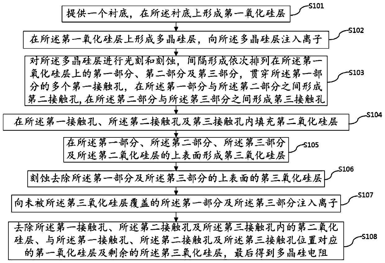
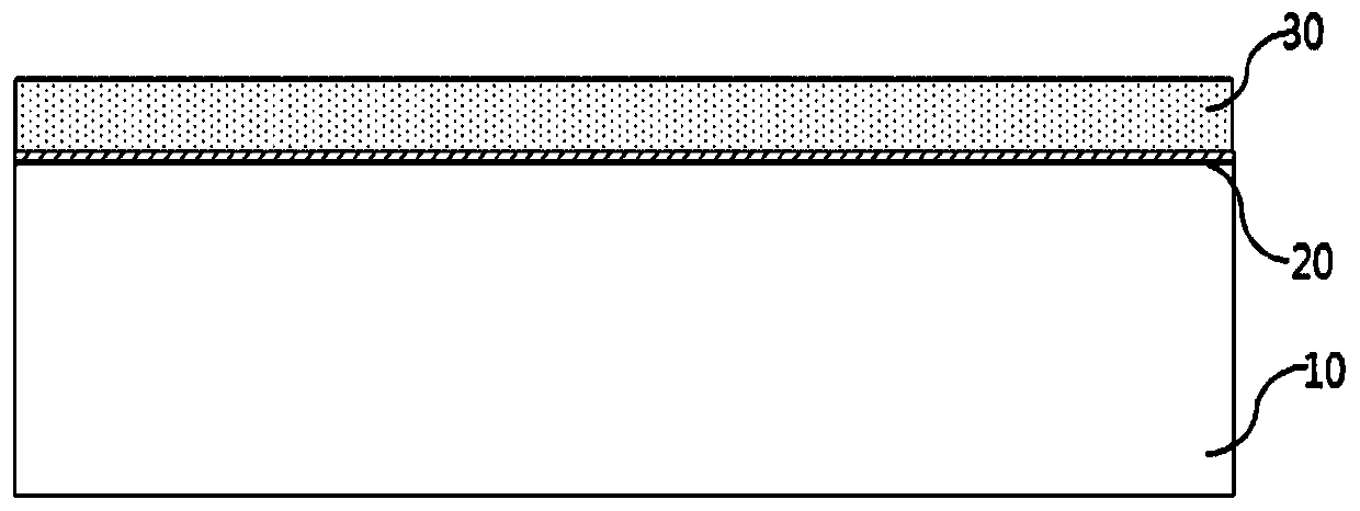
The invention provides a preparation method of a polysilicon resistor, which comprises the following steps: 101, forming a first silicon oxide layer on a substrate; 102: forming a polysilicon layer onthe first silicon oxide layer and implanting ions; 103: forming a first part, a second part and a third part, the first part, the second part and the third part being sequentially arranged on the first silicon oxide layer at intervals, forming a plurality of first contact holes penetrating through the first part, forming a second contact hole between the first part and the second part, forming athird contact hole between the second part and the third part, and filling the second silicon oxide layer; 105: forming a third silicon oxide layer on the first part, the second part, the third part and the second silicon oxide layer; 106: etching to remove the third silicon oxide layer on the first part and the third part, and implanting ions into the first part and the third part; 108: and removing all the second silicon dioxide layers and the third silicon oxide layers. The invention also provides the polysilicon resistor obtained by the above-mentioned preparation method, and the resistance precision and the integration level of the polysilicon resistor are improved.

Description

technical field [0001] The invention relates to the technical field of semiconductor chip manufacturing technology, in particular to a polysilicon resistor and a preparation method thereof. Background technique [0002] In the semiconductor manufacturing process, polysilicon thin film is an extremely widely used semiconductor material. It is usually used to make the gate of metal oxide semiconductor transistors, because it is usually doped at a high concentration in consideration of the gate speed, and In integrated circuits, polysilicon resistors are also used as resistors. [0003] However, in the existing polysilicon high-resistance structure, it is generally used in the furnace tube, and the polysilicon is doped with phosphorus oxychloride (POCL3). Since the doped ions will diffuse at high temperature, the heavily doped ions will diffuse. To the lightly doped region, it affects the ion concentration of the lightly doped region, thereby affecting the resistance value of ...

Claims


Application Information

Patent Timeline
IPC IPC(8): H01L21/02H01L23/64
Inventor 不公告发明人
Owner 泉州臻美智能科技有限公司
Learn More