Supercharge Your Innovation With Domain-Expert AI Agents!

Dynamic observation device and method for centrifugal machine

An observation device and centrifuge technology, which is used in measurement devices, preparation of test samples, and material analysis by optical means, can solve the problems of poor blood separation quality, failure to observe, and inability to directly observe blood samples. The effect of optimal blood centrifugation quality, excluding the influence of individual differences

Pending Publication Date: 2020-12-11
金西盟(天津)人工智能有限责任公司
View PDF0 Cites 0 Cited by
  • Summary
  • Abstract
  • Description
  • Claims
  • Application Information

AI Technical Summary

Problems solved by technology

In reality, the separation factor used in the same blood separation operation specification is often invariable, and there are individual differences in the source of blood samples, which leads to the fact that the empirical separation factor cannot be well adapted to the existing Different sources of individual blood samples, resulting in poor quality of some blood separation and even waste of blood samples
[0004] At present, the centrifuge is at a relatively high speed during the centrifuge operation, and the high-speed moving centrifuge tube and the blood sample in the centrifuge tube cannot be directly observed
Under normal circumstances, there is only one way to know whether the centrifuge work is completed, and that is to stop the centrifuge. However, starting and stopping the centrifuge is generally slow and stable to facilitate the stratification of components, which is bound to be time-consuming and cumbersome.
However, the change of the blood sample in the centrifuge tube by the operator during the period of starting and stopping of the centrifuge cannot be observed.

Method used


Image

  • Dynamic observation device and method for centrifugal machine

Examples


Embodiment

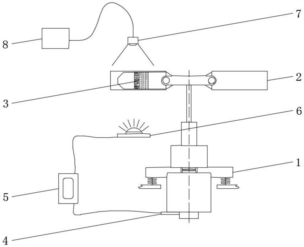
[0028] Example: see figure 1 , the present invention provides a dynamic observation device for a centrifuge, comprising a transparent centrifuge tube 3 for storing blood samples; an image collector 7 positioned above the transparent centrifuge tube 3 for obtaining samples in the transparent centrifuge tube 3 The image of the layered state; the light source 6 is located under the transparent centrifuge tube 3, and is used for supplementing the light of the image collector 7; the bucket 2 is fixed on the rotor of the centrifuge 1, and is used to store the transparent centrifuge tube 3 and allow the light source 6 The generated light passes through; the rotor position sensor 4 is fixed on the rotor for obtaining the angular position signal of the rotor; the strobe trigger module 5 is fixed in the centrifuge 1 for receiving the signal from the rotor position sensor 4 , and is electrically connected to the input end of the light source 6 .

[0029] Wherein, the centrifuge 1 select...


PUM

PropertyMeasurementUnit
Brightnessaaaaaaaaaa

Abstract

The invention relates to the technical field of blood component treatment, and discloses a dynamic observation device and method for a centrifugal machine. The device comprises an image collector, a light source, a bucket, a rotor position sensor, and a stroboscopic trigger module. The invention further discloses a dynamic observation method for the centrifugal machine. The dynamic observation method comprises the following steps that: S1, the centrifugal machine operates; S2, the rotor position sensor generates an angle position signal and transmits the angle position signal to the stroboscopic trigger module, and the stroboscopic trigger module switches on the light source once; S3, the image collector collects an instantaneous picture of a transparent centrifugal tube; S4, the image collector transmits the instantaneous picture to a display; and S5, the instantaneous picture is observed by naked eyes, and the centrifugal state of a sample is judged. The stroboscopic trigger module triggers the light source to supplement light for the image collector, so that the image collector can capture a clear instantaneous picture of the transparent centrifuge tube, and an operator can judge the centrifugation progress of the blood sample conveniently.

Description

technical field [0001] The invention relates to the technical field of blood component processing, in particular to a dynamic observation device and method for a centrifuge. Background technique [0002] The current cell technology has been developed rapidly, and the research and application of cell technology still has a lot of space. A necessary step in the research and application of cell technology is the acquisition of stem cells or immune cells. For example, umbilical cord blood stem cells and peripheral blood mononuclear cells are obtained by centrifugal separation of umbilical cord blood or peripheral blood. The quality and efficiency of centrifugal separation directly affect the results of related research work and applications. [0003] The quality of blood centrifugation is affected by many aspects of the centrifugal factor of the centrifuge. Generally, the more stable the centrifuge is running, the more appropriate the centrifugal force is, and controlling the...

Claims


Application Information

Patent Timeline
IPC IPC(8): G01N21/01G01N21/84G01N1/28H05B45/305
CPCG01N21/01G01N21/84G01N1/28H05B45/305G01N2021/0112
Inventor 李灵溪
Owner 金西盟(天津)人工智能有限责任公司
Features
  • R&D
  • Intellectual Property
  • Life Sciences
  • Materials
  • Tech Scout
  • Unparalleled Data Quality
  • Higher Quality Content
  • 60% Fewer Hallucinations
Learn More