An experimental device for simulating the excavation of tunnels crossing faults

A technology of tunnel excavation and experimental device, applied in the field of tunnel testing, can solve the problems of large deviation of test results, blockage of jack volume, limited number of steel plates, etc., and achieve the effect of avoiding shear damage, improving flexibility and continuous force.

Active Publication Date: 2022-03-11
SOUTHWEST PETROLEUM UNIV
View PDF9 Cites 0 Cited by
  • Summary
  • Abstract
  • Description
  • Claims
  • Application Information

AI Technical Summary

Problems solved by technology

Now relevant research mainly relies on simulation experiments and a variety of related simulation test devices have appeared, but there are some problems, such as the displacement synchronization control device and test method of the patent CN201610004012.0 for simulating tunnels crossing active faults, the buried depth of the tunnel, etc. The parameter is single and the control accuracy is not high, and the deviation of the test result is large; the patent CN201720868943.5 proposes a simulation experiment device for tunnel excavation across faults to solve this problem. Uneven surrounding rock pressure caused by elevation differences; the thickness and inclination of the fault can be flexibly controlled through gauze to obtain a more realistic fault model. This solution can study the quantitative impact of fault geology on the tunnel by controlling a single variable
However, there are still some problems: for example, it uses several short steel plates to exert pressure on the surrounding rock, and the short steel plates are supported by jacks to exert pressure. The number of steel plates is small, and the volume of the jack itself hinders and the space is limited. The pressure in the local subdivision area cannot be adjusted. At the same time, the short steel plate is arranged longitudinally along the experimental box, and the horizontal pressure cannot be adjusted at all.

Method used


Image

  • An experimental device for simulating the excavation of tunnels crossing faults
  • An experimental device for simulating the excavation of tunnels crossing faults
  • An experimental device for simulating the excavation of tunnels crossing faults

Examples


Embodiment 1

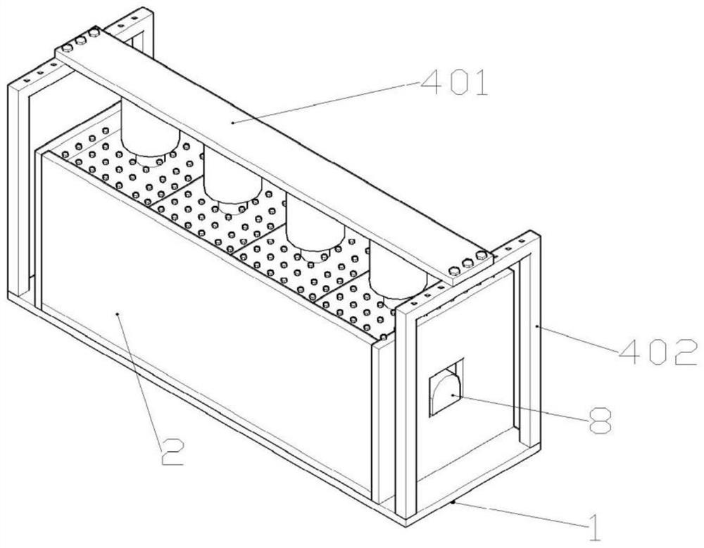
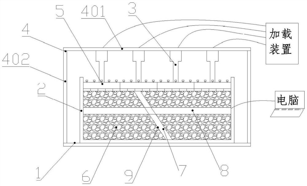
[0035] Such as figure 1 , figure 2 As shown, the present invention is an experimental device for simulating the excavation of tunnels crossing faults, including a substrate 1, a test box 2, a loading structure 3, a support structure 4, a force-transmitting steel plate 5, surrounding rock simulation materials 6, fault simulation materials 7 and Tunnel lining model 8, wherein, the test box 2 and its internal settings belong to the prior art, and will only be briefly described here; the test box 2 is a box-like structure without a cover, and the test box 2 is filled with surrounding rock simulation materials 6 and fault simulation material 7; surrounding rock simulation material 6 and fault simulation material 7 are separated by a gauze 9, that is, the gauze 9 can be used to control the thickness and inclination of the fault; the tunnel lining model 8 passes through the surrounding rock along the length direction of the experimental box 2 The simulation material 6 and the fault...

Embodiment 2

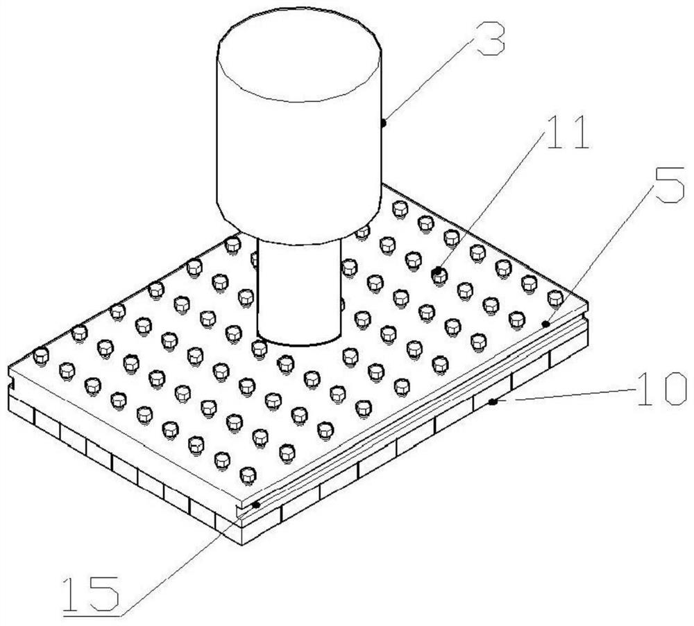
[0038] Such as Figure 3 to Figure 6 As shown, on the basis of Example 1, the force transmission steel plate 5 includes a cover layer 501 and a main body layer 502, the cover layer 501 and the main body layer 502 are connected as one by screws, and the cover layer 501 is A threaded section 503 is provided, and the main body layer 502 is provided with an expanding diameter section 504 and a diameter reducing section 505. The axes of the threaded section 503, the expanding diameter section 504 and the reducing diameter section 505 are all on the same straight line, and the expanding The diameter section 504 is close to the cover plate layer 501, and a connecting rod 12 is arranged in the reducing diameter section 505, and the connecting rod 12 is matched with the inner wall of the reducing diameter section 505, and one end of the connecting rod 12 extends into the expanding diameter section 504, and is connected to The end of the rod 12 located in the enlarged diameter section 5...

Embodiment 3

[0042] On the basis of Embodiment 2, the driving member 11 is a bolt, and the threaded section of the driving member 11 is connected with the threaded section 503 and extends into the enlarged diameter section 504 against the connecting rod 12 for pushing the connecting rod 12 in the axial direction. move.

[0043] The set driver 11 is a bolt, and the bolt includes a head and a screw rod, wherein the screw rod is connected to the threaded section 503 on the cover layer 501 through threads and extends into the enlarged diameter section 504 to contact with the end of the connecting rod 12. The bottom of the screw rod of the part 11 presses against the connecting rod 12 located in the enlarged diameter section 504. When the driving part 11 is rotated, under the cooperation of the screw rod of the driving part 11 and the threaded section 503, the connecting rod 12 can be pushed to drive the force transmission block 10 moves away from the force transmission steel plate 5, which rea...


PUM


Abstract

The invention discloses an experimental device for simulating the excavation of a tunnel crossing a fault, comprising a test box body, a loading structure, a support structure, a force-transmitting steel plate, surrounding rock simulation materials, fault simulation materials, and a tunnel lining model; the experiment box body is without a cover Box-shaped structure; surrounding rock simulation materials, fault simulation materials, and tunnel lining models are all located in the experimental box; the tunnel lining model is equipped with differential digital display displacement gauges and strain-type earth pressure cells on the outside of the primary lining; one end of the loading structure is connected to the The support structure is connected, and the other end is connected to the force-transmitting steel plate; the force-transmitting steel plate is facing the opening surface of the experimental box, and is used to squeeze the surrounding rock simulation material in the experimental box. In the present invention, a plurality of pressure transmission blocks are movably connected to the bottom surface of the force transmission steel plate, and the pressure transmission block is driven by the driving member to move axially along the force transmission steel plate, and squeezes the surrounding rock simulation material in the experimental box, thereby adjusting the surrounding rock simulation material The local pressure improves the flexibility of experiment parameter adjustment.

Description

technical field [0001] The invention relates to the technical field of tunnel tests, in particular to an experimental device for simulating excavation of tunnels crossing faults. Background technique [0002] Before tunnel construction, it is often necessary to study construction mechanics, surrounding rock failure law and surrounding rock stability of fault fracture zone. Now relevant research mainly relies on simulation experiments and a variety of related simulation test devices have appeared, but there are some problems, such as the displacement synchronization control device and test method of the patent CN201610004012.0 for simulating tunnels crossing active faults, the buried depth of the tunnel, etc. The parameter is single and the control accuracy is not high, and the deviation of the test result is large; the patent CN201720868943.5 proposes a simulation experiment device for tunnel excavation across faults to solve this problem. Uneven surrounding rock pressure c...

Claims


Application Information

Patent Timeline
Patent Type & Authority Patents(China)
IPC IPC(8): G01N33/24
CPCG01N33/24
Inventor 王浩权张军伟钱进李雪郭亮曲宏略纪佑军
Owner SOUTHWEST PETROLEUM UNIV
Why Eureka
Try Eureka