Connection detection circuit and method and electric equipment

A technology for electrical equipment and connection detection, applied in electrical connection testing, measuring current/voltage, measuring electrical variables, etc., can solve the problems of inaccurate connection detection and inability to detect in real time, and achieve the effect of improving detection accuracy

Pending Publication Date: 2020-12-11
GREE ELECTRIC APPLIANCES INC
View PDF0 Cites 5 Cited by
  • Summary
  • Abstract
  • Description
  • Claims
  • Application Information

AI Technical Summary

Problems solved by technology

[0005] Embodiments of the present invention provide a connection detection circuit, method and electrical

Method used


Image

  • Connection detection circuit and method and electric equipment
  • Connection detection circuit and method and electric equipment
  • Connection detection circuit and method and electric equipment

Examples


Embodiment 1

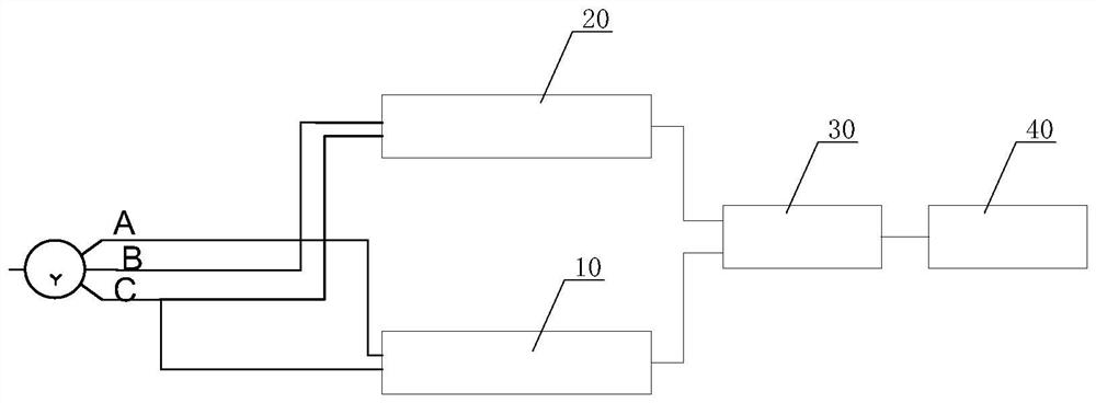
[0064] This embodiment provides a connection detection circuit, figure 1 It is a structural diagram of a connection detection circuit according to an embodiment of the present invention, such as figure 1 As shown, the connection detection circuit includes:

[0065] The first detection module 10, the input end of the first detection module 10 is connected between the first terminal A and the third terminal C of the electrical equipment, and the output end of the first detection module 10 is connected to the logical operation module; the second detection module 20 , the input end of the second detection module 20 is connected between the second terminal B and the third terminal C of the electrical equipment, and the output end of the second detection module 20 is also connected to the logic operation module; wherein, the first terminal A, The second terminal B and the third terminal C are respectively used to connect the three fire wires L1, L2, L3 of the power supply system; t...

Embodiment 2

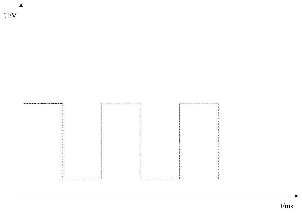
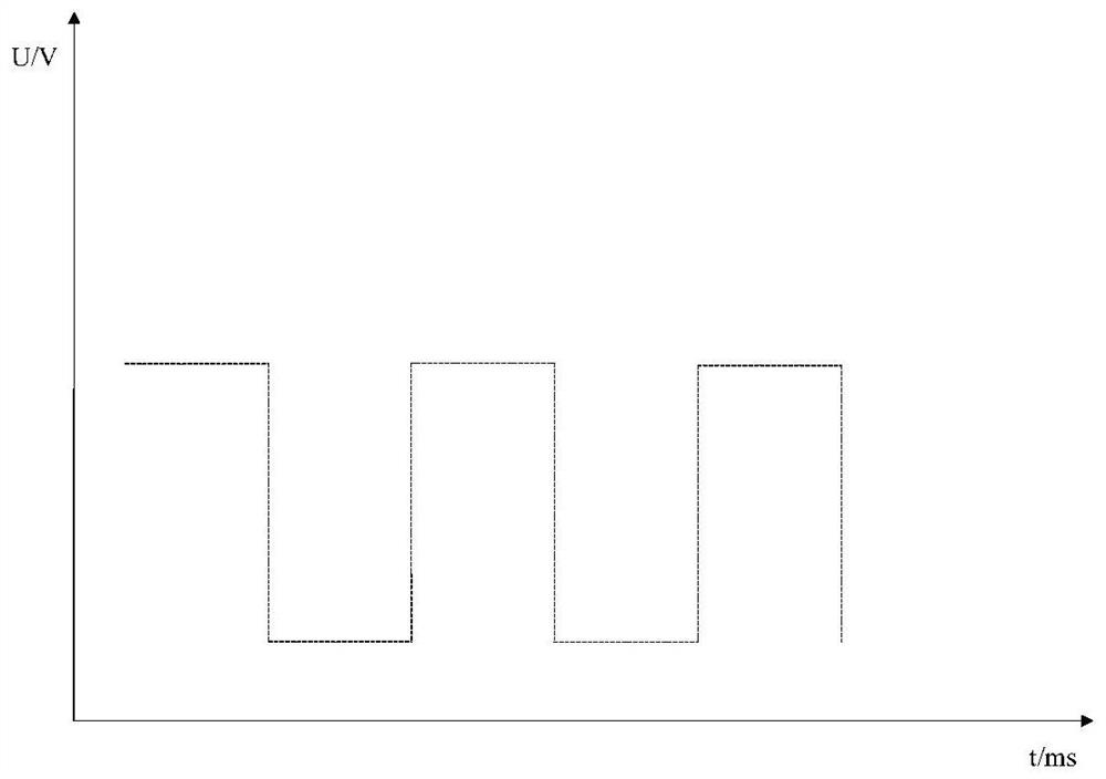
[0072] This embodiment provides another connection detection circuit, Figure 5 is a structural diagram of a connection detection circuit according to another embodiment of the present invention, such as Figure 5 As shown, the above-mentioned logical operation module 30 includes:

[0073] Exclusive OR gate chip IC1, exclusive OR gate chip IC1 is used to output low level when the signals output by the first detection module 10 and the second detection module 20 are the same; When the signal is opposite, output high level. The judging module 40 is specifically used to judge whether the duty ratio of the PWM signal is within a first preset range; when the duty ratio is within the first preset range, it is determined that the connection relationship of the electrical equipment is normal; When the duty ratio is not within the first preset range, it is determined that the connection relationship of the electrical equipment is abnormal.

[0074] For example, when the terminals of...

Embodiment 3

[0093] This embodiment provides another connection detection circuit, Figure 10 is a structural diagram of a connection detection circuit according to another embodiment of the present invention, such as Figure 10 As shown, in this embodiment, the first resistor R1, the second resistor R2, the third resistor R3, and the fourth resistor R4 have a resistance value of 500Ω, the fifth resistor R5 and the ninth resistor R9 have a resistance value of 1MΩ, and the sixth resistor R5 has a resistance value of 1MΩ. The resistance value of the resistor R6 and the tenth resistor R10 is 2.4kΩ, the resistance value of the seventh resistor R7, the eighth resistor R8, the eleventh resistor R11, the twelfth resistor R12, the thirteenth resistor R13 and the fourteenth resistor R14 Both are 10kΩ.

[0094] The models of the first comparator A1 and the second comparator A2 are both LMC7211BIM5, the models of the first operational amplifier U1 and the second operational amplifier U2 are both LM2...


PUM


Abstract

The invention discloses a connection detection circuit, method and electric equipment. The circuit comprises a first detection module, a second detection module, a logic operation module and a judgment module, wherein the input end of the first detection module is connected between a first terminal and a third terminal of electric equipment, and the output end of the first detection module is connected with the logical operation module; the input end of the second detection module is connected between the second terminal and the third terminal of the electric equipment, and the output end of the second detection module is connected with the logical operation module; the logic operation module is used for generating PWM signals according to the signals output by the first detection module and the second detection module; and the judgment module is used for judging whether the connection relationship of the electric equipment is abnormal or not according to the duty ratio of the PWM signal. Through the method and the device, the influence of voltage fluctuation on a judgment result can be avoided, the detection accuracy is improved, meanwhile, whether the connection relationship is abnormal or not can be judged through a single period, and real-time detection is realized.

Description

technical field [0001] The invention relates to the technical field of electronic circuits, in particular to a connection detection circuit, method and electrical equipment. Background technique [0002] For refrigeration electrical equipment and devices that use three-phase electricity, in the load circuit powered by AC power, if a certain phase of the electrical equipment is connected to the neutral line by mistake, or a certain phase is not connected, these will cause the load It cannot work normally, so it is necessary to detect whether the input connection relationship of the AC power supply is normal by protecting the electrical equipment at the front end of the power supply. When the neutral line N goes up, it is necessary to report a fault at this time and cut off the load circuit of the subsequent stage at the same time; if there is a phase loss in the three phases of the AC power supply, it should also report a fault and cut off the load circuit of the subsequent s...

Claims


Application Information

Patent Timeline
IPC IPC(8): G01R31/67G01R19/165
CPCG01R19/16557G01R31/67
Inventor 胡江沈丽凤钱沛周葆林
Owner GREE ELECTRIC APPLIANCES INC
Why Eureka
Try Eureka