Optical fiber coupling alignment structure and preparation method, optical fiber coupling method

An optical fiber coupling and optical fiber technology, which is applied in the coupling of optical waveguides, opto-mechanical equipment, optics, etc., can solve the problems of difficult to achieve effective optical fiber alignment, difficult processing methods, and difficult to improve coupling efficiency, and is conducive to accurate alignment. Effect

Active Publication Date: 2021-07-20
SHENZHEN CONJUGATE TECH CO LTD
View PDF0 Cites 0 Cited by
  • Summary
  • Abstract
  • Description
  • Claims
  • Application Information

AI Technical Summary

Problems solved by technology

[0006] In view of the shortcomings of the prior art described above, the purpose of the present invention is to provide a fiber coupling alignment structure and preparation method, and a method for coupling an optical fiber to an optical component, which are used to solve the problem of complex fiber coupling methods and poor coupling efficiency in the prior art. It is difficult to improve, it is difficult to achieve effective alignment of optical fibers, and it is difficult to be compatible with existing processing methods such as MEMS.

Method used


Image

  • Optical fiber coupling alignment structure and preparation method, optical fiber coupling method
  • Optical fiber coupling alignment structure and preparation method, optical fiber coupling method
  • Optical fiber coupling alignment structure and preparation method, optical fiber coupling method

Examples


Embodiment Construction

[0068] The embodiments of the present invention are described below through specific specific examples, and those skilled in the art can easily understand other advantages and effects of the present invention from the contents disclosed in this specification. The present invention can also be implemented or applied through other different specific embodiments, and various details in this specification can also be modified or changed based on different viewpoints and applications without departing from the spirit of the present invention.

[0069] When describing the embodiments of the present invention in detail, for the convenience of explanation, the cross-sectional views showing the device structure will not be partially enlarged according to the general scale, and the schematic diagrams are only examples, which should not limit the protection scope of the present invention. In addition, the three-dimensional spatial dimensions of length, width and depth should be included i...


PUM

PropertyMeasurementUnit
thicknessaaaaaaaaaa
thicknessaaaaaaaaaa
thicknessaaaaaaaaaa

Abstract

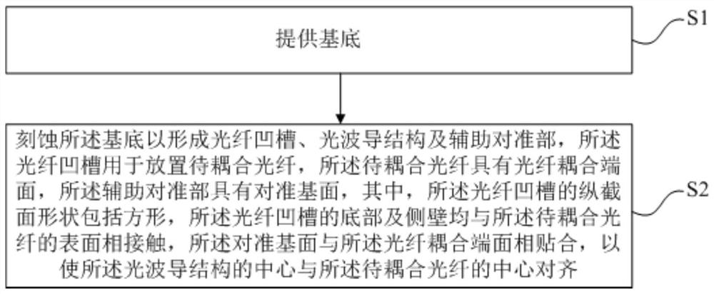
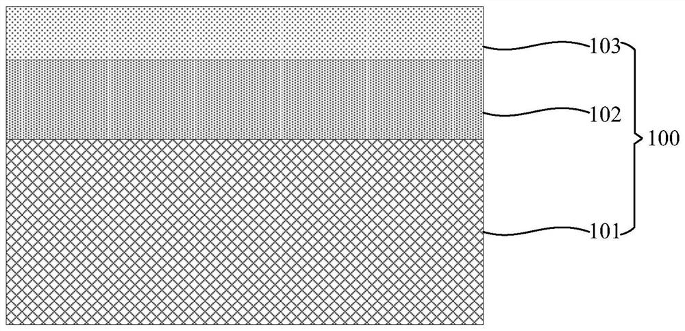
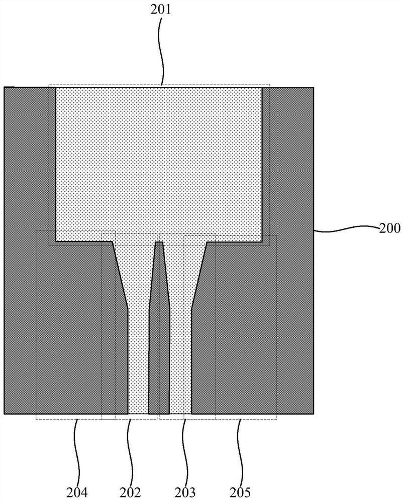
The invention provides an optical fiber coupling alignment structure from an optical fiber to an optical waveguide structure, a preparation method and a method for coupling an optical fiber to an optical component. The preparation method of the optical fiber coupling alignment structure includes: preparing an optical fiber groove and an optical waveguide structure in a substrate And the auxiliary alignment part, the longitudinal cross-sectional shape of the optical fiber groove includes a square, the alignment base surface of the auxiliary alignment part fits the coupling end face of the optical fiber, the three sides of the optical fiber groove are in contact with the optical fiber to be coupled, and the optical fiber to be coupled Up and down and left and right will be automatically aligned with the optical waveguide structure, and the optical fiber groove with a square cross-section whose side wall is perpendicular to the bottom of the present invention can be prepared based on a dry etching process, so that the preparation of the optical fiber alignment coupling structure is comparable to other processes ( Compatible with the MEMS process), the size of the optical fiber groove can be flexibly controlled according to the size of the optical fiber. The present invention can form the optical fiber groove, the optical waveguide structure and the auxiliary alignment part based on the same photolithographic etching process, which is beneficial to the precise alignment between the optical fiber to be coupled and the optical waveguide structure.

Description

technical field [0001] The invention belongs to the field of optical fiber signal transmission, and in particular relates to an optical fiber coupling alignment structure and a preparation method thereof, and a method for coupling optical fibers to optical components. Background technique [0002] In the signal transmission process of the optical fiber, the optical fiber needs to be coupled and aligned with the active or passive optoelectronic device, so as to realize the signal transmission process. For example, optical fibers that transmit information using electromagnetic signals at infrared wavelengths must be coupled with silicon photonic chips or other optical components, that is, correctly installed in precise alignment positions to ensure that there is a high enough coupling efficiency between the optical fiber and the silicon photonics chip for correct operation. signal transmission. The two exit ends of each fiber need to be properly aligned at the corresponding p...

Claims


Application Information

Patent Timeline
Patent Type & Authority Patents(China)
IPC IPC(8): G02B6/36G03F1/00G03F7/00G02B6/136
CPCG02B6/136G02B6/3636G02B6/3692G03F1/00G03F7/0005
Inventor 任恒江罗杰杨帆
Owner SHENZHEN CONJUGATE TECH CO LTD
Why Eureka
Try Eureka