
Winding type iron core magnetically controlled saturated reactor

A reactor, winding technology, applied in the direction of variable inductors, inductors, variable transformers, etc., can solve the problems of poor overload capacity of solenoid valve controllable reactors, and achieve simple structure and easy processing. , control simple effects

Inactive Publication Date: 2015-05-13
SOUTHEAST UNIV
View PDF4 Cites 1 Cited by
  • Summary
  • Abstract
  • Description
  • Claims
  • Application Information

AI Technical Summary

Problems solved by technology

However, because its capacity has reached the limit value, the overload capacity of the magnetic valve controllable reactor is poor.

Method used


Image

  • Winding type iron core magnetically controlled saturated reactor
  • Winding type iron core magnetically controlled saturated reactor
  • Winding type iron core magnetically controlled saturated reactor

Examples


Embodiment Construction

[0019] The present invention will be further described below in conjunction with the accompanying drawings.

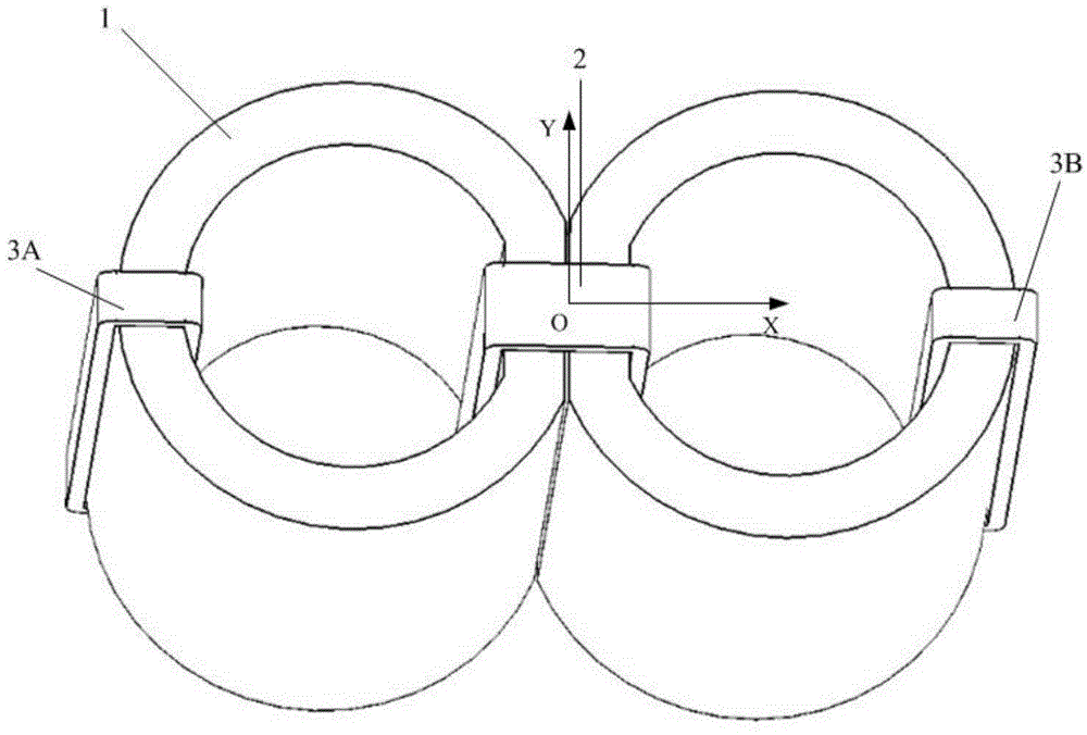
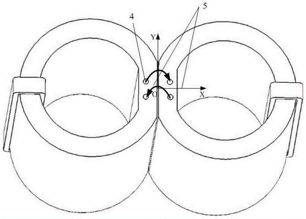
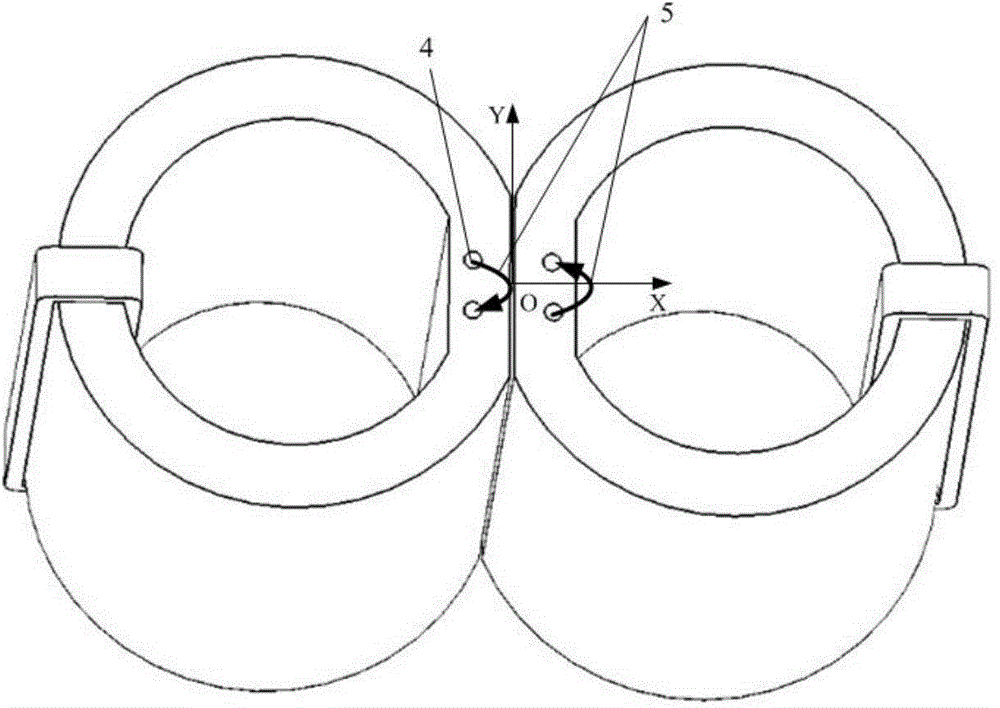
[0020] Such as figure 1 A coiled iron core magnetically saturated controllable reactor is shown, including two reactor cores 1 with the same size and structure, an AC working winding 2, two sets of DC excitation windings 3, and two sets of local saturation windings 5; the two One side of the reactor core 1 is placed close to each other, and the contact surface of the two reactor cores 1 is a rectangular plane; a rectangular coordinate system is established, and the line connecting the center points of the two reactor cores 1 is the X axis, and the two centers The middle position of the point is the origin to establish the Y axis; the two reactor cores 1 are symmetrical to the Y axis; the upper surfaces of the two reactor cores 1 at the position of the contact surface are provided with the same number of local saturated Winding holes 4, and the distance between adjacen...


PUM


Abstract

The invention discloses a winding type iron core magnetically controlled saturated reactor, and belongs to a power grid automatic reactive power compensation device. The reactor comprises winding type iron cores, an alternating-current working winding, direct-current exciting windings and partial saturation windings. The iron cores include the two winding type iron cores which are adjacently placed. The alternating-current working winding is wound around the adjacent portions of the iron cores and wound on the two iron cores. The two direct-current exciting windings are connected in series and symmetrically wound on the two iron cores respectively. Four symmetrical holes in the same size are reserved in the adjacent portions of the two iron cores. The partial saturation windings penetrate through the holes to be wound on the iron cores and are used for generating partial saturation equivalent gas gaps. The adjustable reactor is simple in structure and easy to machine, the linear regulation range of the reactance value is wide, and the large overload capacity is achieved.

Description

technical field [0001] The invention relates to a reactor, in particular to a coiled core magnetic saturation controllable reactor. Background technique [0002] In high-voltage and ultra-high-voltage power grids, the purpose of reactive power compensation is to support the voltage of the grid pivot point, improve the stability of the grid, increase the transmission capacity of the line and reduce the line loss, suppress the power oscillation of the grid and the power frequency overvoltage, and adjust the voltage. And optimize reactive power flow, etc. Reactive power balance is an important guarantee for the safe, stable and economical operation of the power grid, especially for the ultra-high voltage long-distance transmission network. Studies have proved that the capacity of the adjustable reactor can not only change with the size of the transmission power, smoothly adjust the reactive power of the system, realize flexible power transmission, but also suppress power frequ...

Claims


Application Information

Patent Timeline
IPC IPC(8): H01F29/00H01F27/24H01F27/28H01F27/30H02J3/18
CPCY02E40/30
Inventor 林克曼李念林明耀
Owner SOUTHEAST UNIV
Learn More