
A kind of preparation method of laminated board

A technology of lamination and thermoforming, applied in the direction of lamination, lamination equipment, chemical instruments and methods, etc., can solve the problems of high density of glue formula filler, high thermal conductivity, increase the thickness of multi-layer boards, etc., to achieve flexibility Distribution state, good economic benefits, and the effect of improving the infiltration effect

Active Publication Date: 2015-12-30
SHENGYI TECH SUZHOU
View PDF5 Cites 1 Cited by
  • Summary
  • Abstract
  • Description
  • Claims
  • Application Information

AI Technical Summary

Problems solved by technology

The problem in the traditional multilayer board manufacturing process with thick copper structure is: the huge difference in thermal conductivity between copper foil and resin makes the surface resin accumulate a lot of heat under thermal shock, and the thermal expansion coefficients of resin and copper foil are inconsistent. As a result, a huge tensile stress is generated between the copper foil and its adjacent layer of resin due to the difference in expansion. When the tensile stress exceeds the bonding force between the resin and the copper foil, a layered explosion on the macroscopic surface is produced.
[0004] However, although the first method can slightly reduce the probability of delamination, it is easy to delaminate at the interface due to insufficient bonding force due to the limited bonding force between the organic dielectric layer and copper foil and resin; in addition, this The method significantly increases the thickness of the multilayer board, which is not suitable for PCB products with strict thickness tolerance requirements; at the same time, the organic dielectric layer with high thermal conductivity uses special materials with high thermal conductivity, and the material cost is very high, which does not have economic benefits
In the second method, because the thermal expansion coefficient of the filler is small, increasing the proportion of the filler can reduce the overall thermal expansion coefficient of the resin, thereby reducing the differential stress of thermal expansion and reducing delamination; however, since the filler is evenly distributed in the laminate Internally, if the surface layer resin has a large filler distribution density, it is necessary to greatly increase the total filler addition ratio; and the consequence of this approach is that the glue formula filler density is too high, and the semi-cured production process is difficult to achieve, even if the production The prepreg with such a high filler ratio will also face the problem of uneven filler distribution in the laminate; at the same time, the multilayer circuit board will have poor processing adaptability due to the brittleness of the board; however, in this method, When the thermosetting resin is based on 100 parts, the filler content must be more than 100 parts. If the filler is added less, the effect of reducing delamination and bursting will not be achieved.
[0005] For manufacturers of printed circuit boards, how to produce multilayer boards with thick copper structures that can meet the reliability requirements of multilayer printed circuit boards such as electrical, mechanical, and heat resistance, while avoiding the The delamination explosion caused by the difference in thermal conductivity and thermal expansion coefficient between resin and copper foil has become a goal that those skilled in the art have been eager to achieve but have not been able to solve well.

Method used


Image

  • A kind of preparation method of laminated board
  • A kind of preparation method of laminated board
  • A kind of preparation method of laminated board

Examples


Embodiment 1~2

[0043] Prepare laminates such as Figure 1~2 As shown, it includes the following steps:

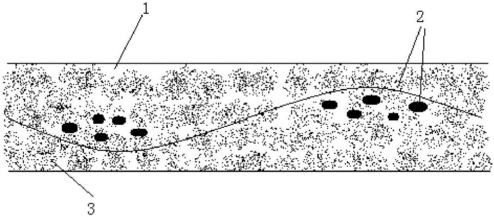
[0044] First: prepare a prepreg, prepare a thermosetting resin glue solution according to the data in Table 1, then impregnate the glass fiber cloth in the above glue solution, and heat and dry the impregnated glass fiber cloth to obtain a prepreg, see figure 1 As shown, there are resin 1, glass fiber cloth 2, and filler 3 in the prepreg; the heating and drying process conditions are baking at 100-200°C for 1-10 minutes;

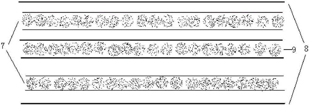
[0045] Second: After superimposing 4 pieces of the above prepregs, cover them with 70 micron copper foil on both sides for lamination, and hot press forming to obtain the laminate, wherein the lamination process conditions are 0.2-2MPa pressure and 180- Press at 250°C for 2 to 4 hours. figure 2 It is a schematic diagram of the laminate effect in the embodiment of the present invention.

[0046] During the lamination process, electrodes are arranged on the outer surf...

Embodiment 3

[0048] Prepare laminated board, it comprises the steps:

[0049]First: prepare a prepreg, prepare a thermosetting resin glue solution according to the data in Table 1, then impregnate the glass fiber cloth in the above glue solution, and heat and dry the impregnated glass fiber cloth to obtain a prepreg, wherein heating and drying The process condition is to bake at a temperature of 100-200°C for 1-10 minutes;

[0050] Second: take 4 above-mentioned prepregs and superimpose them, cover them with 70 micron copper foil on one side, attach an aluminum block on the other side for lamination, and heat press forming to obtain the laminated board, wherein the lamination process conditions are Pressing at a pressure of 0.2-2MPa and a temperature of 180-250°C for 2-4 hours.

[0051] During the lamination process, electrodes are arranged on the outer surface of the copper foil to form an electric field.

Embodiment 4

[0053] Prepare the laminate, and prepare the thermosetting resin glue solution according to the data in Table 1;

[0054] Coating glue on the rough surface of 70 micron copper foil, then attaching another 70 micron copper foil on the rough surface, and forming by hot pressing, the laminate can be obtained, wherein the lamination process conditions are 0.2-2MPa pressure and 180-250 Press at ℃ for 2-4 hours.

[0055] During the lamination process, electrodes are arranged on the outer surface of the copper foil to form an electric field.

[0056] The composition of table 1 embodiment and comparative example

[0057]

[0058]

[0059] Note: The above data are based on solid weight.

[0060] Use the laminated board that makes in embodiment 1~4 to manufacture core plate, according to image 3 Laminate according to the stacking method shown, and laminate according to the curing conditions required by the resin type of the four-layer printed circuit board, and perform thermal...


PUM

PropertyMeasurementUnit
thicknessaaaaaaaaaa

Abstract

The invention discloses a method for manufacturing a laminated board. The method for manufacturing the laminated board comprises the following steps: (1) adding a filler into thermosetting resin to obtain a resin composition, dissolving the resin composition with a solvent to obtain glue, and directly combining the glue, a reinforcing material and a metal foil to obtain a combined module, wherein the filler comprises a charged filler and a non-charged filler; (2) performing hot forming on the combined module to obtain the laminated board, wherein in the hot forming process of the combined module, the combined module is always in an electrical field. In the method, the charged filler is added into a glue formulation of the laminated board, and in the laminating process, the electrical field is used for manufacturing the laminated board, so that the problem of hierarchical burst of the laminated board caused by too large diffidence of thermal expansion coefficients and thermal conductivity coefficients of the resin and a copper foil is solved; experiments show that the defective rate, caused by the hierarchical burst, of the laminated board manufactured by the invention method is 0%, so that the problem of the hierarchical burst is solved.

Description

technical field [0001] The invention relates to a preparation method of a laminated board, which belongs to the technical field of electronic materials. Background technique [0002] With the development of the electrical industry, copper clad laminates for printed circuits have also achieved rapid development. The problem in the traditional multilayer board manufacturing process with thick copper structure is: the huge difference in thermal conductivity between copper foil and resin makes the surface resin accumulate a lot of heat under thermal shock, and the thermal expansion coefficients of resin and copper foil are inconsistent. As a result, a huge tensile stress is generated between the copper foil and its adjacent layer of resin due to the difference in expansion. When the tensile stress exceeds the bonding force between the resin and the copper foil, a macroscopic layer explosion occurs. [0003] In view of the above problems, in order to reduce delamination explosio...

Claims


Application Information

Patent Timeline
Patent Type & Authority Patents(China)
IPC IPC(8): B32B37/06B32B37/10B32B15/08B32B27/04B32B27/20
Inventor 胡浩孙凛张泰林黄昕和崔春梅李俊
Owner SHENGYI TECH SUZHOU
Learn More