
Coal pressure reduction calculation method and system for heat supply substitution of combined heat and power generation unit

A cogeneration unit and calculation method technology, applied in calculations, complex mathematical operations, instruments, etc., can solve the problem of high thermal efficiency, the lack of an accurate calculation method for the reduction of coal combustion, and the inability to scientifically evaluate the reduction of coal combustion in the whole society Effect and other issues, to achieve the effect of easy operation, simple calculation process and accurate calculation results

Pending Publication Date: 2020-12-11
ELECTRIC POWER RESEARCH INSTITUTE OF STATE GRID SHANDONG ELECTRIC POWER COMPANY +1
View PDF0 Cites 0 Cited by
  • Summary
  • Abstract
  • Description
  • Claims
  • Application Information

AI Technical Summary

Problems solved by technology

[0004] According to the inventor's understanding, the current urban central heating mainly includes several heating methods such as large-scale cogeneration units (generally above 200MW), small-scale cogeneration units (generally below 50MW), small coal-fired boilers, and small coal-fired boilers. Boilers and small cogeneration units have low efficiency, while large cogeneration units have high thermal efficiency. Using high-efficiency cogeneration units to replace low-efficiency small coal-fired boilers and small cogeneration units for heat supply is an important way to reduce coal consumption. However, at this stage, there is no accurate calculation method for the reduction of coal consumption after replacing small cogeneration units with large cogeneration units for heat supply, and it is impossible to scientifically evaluate the effect of reducing coal consumption in the whole society after heating replacement.

Method used


Image

  • Coal pressure reduction calculation method and system for heat supply substitution of combined heat and power generation unit
  • Coal pressure reduction calculation method and system for heat supply substitution of combined heat and power generation unit
  • Coal pressure reduction calculation method and system for heat supply substitution of combined heat and power generation unit

Examples


Embodiment Construction

[0039] The present disclosure will be further described below in conjunction with the embodiments.

[0040] It should be noted that the following detailed description is exemplary and intended to provide further explanation of the present disclosure. Unless defined otherwise, all technical and scientific terms used herein have the same meaning as commonly understood by one of ordinary skill in the art to which this disclosure belongs.

[0041] It should be noted that the terminology used herein is only for describing specific embodiments, and is not intended to limit the exemplary embodiments according to the present disclosure. As used herein, unless the context clearly dictates otherwise, the singular is intended to include the plural, and it should also be understood that when the terms "comprising" and / or "comprising" are used in this specification, they mean There are features, steps, operations, means, components and / or combinations thereof.

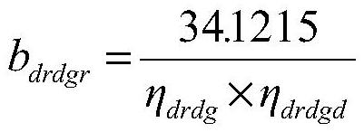
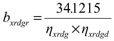
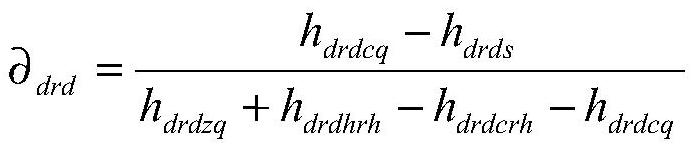
[0042] In this embodiment...


PUM


Abstract

The invention provides a coal pressure reduction calculation method and a coal pressure reduction calculation system for heat supply substitution of a combined heat and power generation unit, which divide coal consumption of the combined heat and power generation unit into heat supply coal consumption and power generation coal consumption on the premise of ensuring balance of total heat and totalelectric quantity of a whole area. The heat supply and power generation coal consumption of large and small combined heat and power generation units is calculated respectively, then the total coal pressure reduction after full-area heat supply substitution is calculated, operation is easy, and the calculation result is accurate.

Description

technical field [0001] The disclosure belongs to the technical field of energy calculation, and in particular relates to a calculation method and system for coal-fired pressure reduction for heating replacement of cogeneration units. Background technique [0002] The statements in this section merely provide background information related to the present disclosure and do not necessarily constitute prior art. [0003] Coal consumption for heating in winter accounts for a very large proportion of total coal consumption, and coal is the main energy source for heating in some areas. [0004] According to the inventor's understanding, the current urban central heating mainly includes several heating methods such as large-scale cogeneration units (generally above 200MW), small-scale cogeneration units (generally below 50MW), small coal-fired boilers, and small coal-fired boilers. Boilers and small cogeneration units have low efficiency, while large cogeneration units have high th...

Claims


Application Information

Patent Timeline
IPC IPC(8): G06F17/10G06Q50/06
CPCG06F17/10G06Q50/06
Inventor 祝令凯丁俊齐张海静郑威王为帅王倩郭俊山韩悦商攀峰
Owner ELECTRIC POWER RESEARCH INSTITUTE OF STATE GRID SHANDONG ELECTRIC POWER COMPANY
Features
  • Generate Ideas
  • Intellectual Property
  • Life Sciences
  • Materials
  • Tech Scout
  • Unparalleled Data Quality
  • Higher Quality Content
  • 60% Fewer Hallucinations
Learn More